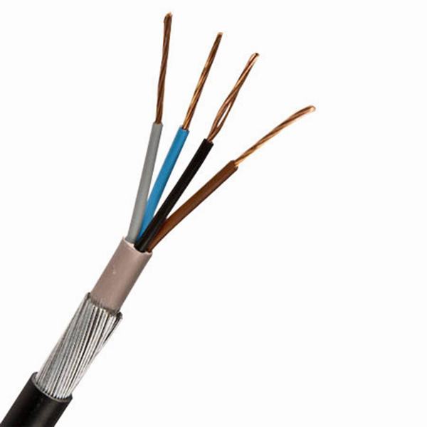
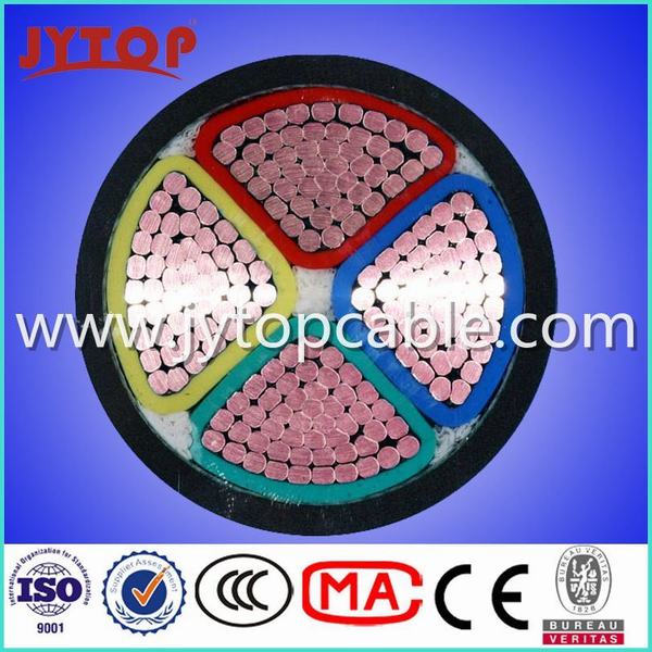
0.6/1kv 16mm 4 Core Copper PVC Insulated Swa Armored Cable
0.6/1kv 16mm 4 Core Copper PVC Insulated Swa Armored Cable image
Get Latest Price Request a quote
Quick Details
Product Details
0.6/1kv 16mm 4 Core Copper PVC insulated SWA Armored Cable
Application
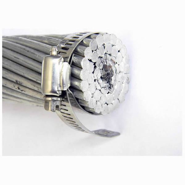
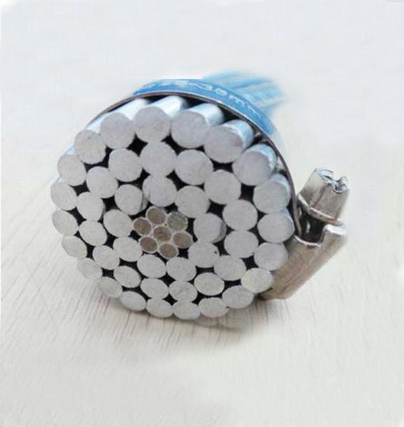
Armored copper cable is a very innovative concept for overhead power distribution as compared to the conventional bare conductor overhead distribution system.
It provides higher level of safety and reliability, lower power losses and ultimate system economy by reducing installation, maintenance and operative cost.
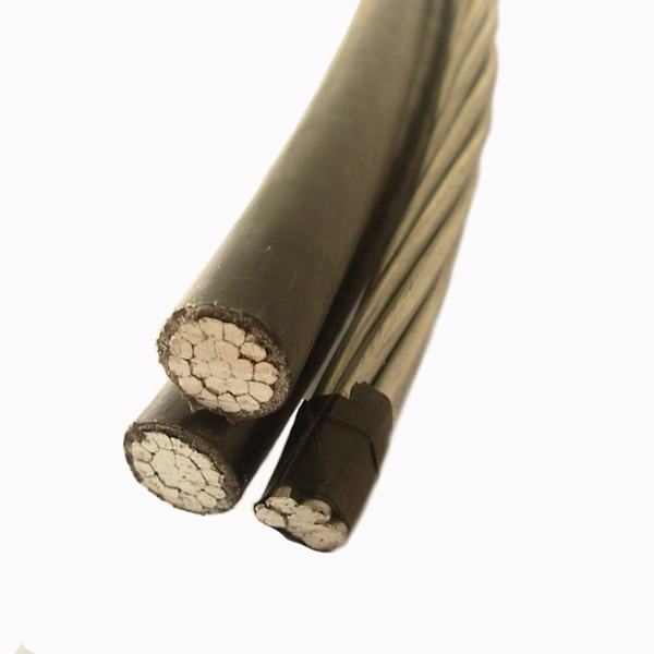
Caledonian LV Aerial Bundle Cables are designed to supply 600/1000 volt aerial service for temporary service at construction sites, as a service drop (power pole to service entrance), as a secondary cable (pole to pole) or street lighting.
This over-head cable provides reinforced insulation acc. IEC 61140 and fulfill therefore Class II acc. IEC 61140. It is not flame retardant. But this could be if requested change to a flame retardant cable.
Standard
Basic design to BS 7870 / TNB Specification(IEC 60502) / HD 626 S1 / NFC 33-209 / AS/NZS 3560-1 standards
Construction
| Conductor | Aluminium conductor, round stranded compressed (RM). |
| Insulation | XPLE compound, UV-resistant. |
| Core Identification | 1, 2 resp. 3 raised longitudinal ribs on the surface of the cores. The surface of the neutral core should have at least 12 ribs for cross-sections up to 50 mm² and a minimum of 16 ribs for cores above 50 mm². In the case of five core bundles the surface of the protective core should be smooth. |
Electrical Properties
| Rated Voltage | 0.6/1kV |
| Test Voltage | 4 Veff kV |
| Minimum Laying Temperature | -20°C |
| Operating Temperature | -40°C~ +90°C |
| Maximum Short-circuit Temperature | 250°C |
| Maximum Conductor Temperature | 80°C |
| Minimum Bending Radius | 18×OD |
Construction Parameters
BS 7870
| Number of Cores x Nominal Cross Section | Overall Diameter | Weight | Maximum Conductor Resistance | Minimum Breaking Load | Current Rating |
|---|---|---|---|---|---|
| No.×mm² | mm | Kg/Km | Ω/Km | KN | A |
| 1×16 RM | 8.0 | 74 | 1.910 | 2.5 | 72 |
| 1×25 RM | 9.0 | 106 | 1.200 | 4.0 | 107 |
| 1×35 RM | 10.5 | 138 | 0.868 | 5.5 | 132 |
| 1×50 RM | 11.8 | 182 | 0.641 | 8.0 | 165 |
| 1×70 RM | 13.0 | 252 | 0.443 | 10.7 | 205 |
| 1×95 RM | 15.4 | 333 | 0.320 | 13.7 | 240 |
| 1×120 RM | 17.0 | 408 | 0.253 | 18.6 | 290 |
| 1×150 RM | 19.0 | 502 | 0.206 | 23.2 | 334 |
| 1×185 RM | 21.0 | 611 | 0.164 | 28.7 | 389 |
| 1×240 RM | 24.0 | 801 | 0.125 | 37.2 | 467 |
| 2×16 RM | 15.6 | 147 | 1.910 | 2.5 | 72 |
| 2×25 RM | 18.0 | 208 | 1.200 | 4.0 | 107 |
| 2×35 RM | 20.0 | 277 | 0.868 | 5.5 | 132 |
| 2×50 RM | 23.5 | 361 | 0.641 | 8.0 | 165 |
| 2×70 RM | 25.4 | 505 | 0.443 | 10.7 | 205 |
| 2×95 RM | 30.3 | 666 | 0.320 | 13.7 | 240 |
| 2×150 RM | 38.0 | 1004 | 0.206 | 23.2 | 334 |
| 4×16 RM | 18.8 | 286 | 1.910 | 2.5 | 72 |
| 4×25 RM | 21.2 | 430 | 1.200 | 4.0 | 107 |
| 4×35 RM | 24.1 | 553 | 0.868 | 5.5 | 132 |
| 4×50 RM | 27.8 | 746 | 0.641 | 8.0 | 165 |
| 4×70 RM | 31.8 | 1009 | 0.443 | 10.7 | 205 |
| 4×95 RM | 37.8 | 1332 | 0.320 | 13.7 | 240 |
| 4×120 RM | 54.4 | 1632 | 0.253 | 18.6 | 290 |
| 4×50 + 1×25 RM | 31.9 | 814 | 0.641/1.200 | 8.0/4.0 | 165/107 |
| 4×50 + 1×35 RM | 31.9 | 845 | 0.641/0.868 | 8.5/5.5 | 165/132 |
| 4×70 + 1×25 RM | 36.0 | 1105 | 0.443/1.200 | 10.7/4.0 | 205/107 |
| 4×70 + 2×25 RM | 40.0 | 1217 | 0.443/1.200 | 10.7/4.0 | 205/107 |
| 4×95 + 1×25 RM | 41.8 | 1438 | 0.320/1.200 | 13.7/4.0 | 240/107 |
| 4×95 + 2×25 RM | 42.0 | 1544 | 0.320/1.200 | 13.7/4.0 | 240/107 |
| 4×120 + 1×25 RM | 59.0 | 2050 | 0.253/1.200 | 18.6/4.0 | 290/107 |
Other cross-sections can be offered upon request.
TNB Specification(IEC 60502)
| Number of Cores x Nominal Cross Section | Overal Diameter | Weight | Maximum Conductor Resistance | Minimum Breaking Load | Current Rating |
|---|---|---|---|---|---|
| No.×mm² | mm | Kg/Km | Ω/Km | KN | A |
| 1×16+1×25 RM | 15.3 | 160 | 1.910 | 2.5 | 72 |
| 3×16+1×25 RM | 19.0 | 290 | 1.200 | 4.0 | 107 |
| 3×25+1×25 RM | 23.2 | 400 | 0.868 | 5.5 | 132 |
| 3×35+1×25 RM | 25.6 | 500 | 0.641 | 8.0 | 165 |
| 3×50+1×35 RM | 30.0 | 680 | 0.443 | 10.7 | 205 |
| 3×70+1×50 RM | 34.9 | 920 | 0.320 | 13.7 | 240 |
| 3×95+1×70 RM | 40.6 | 1270 | 0.253 | 18.6 | 290 |
| 3×120+1×70 RM | 44.1 | 1510 | 0.206 | 23.2 | 334 |
| 3×150+1×95 RM | 49.2 | 1870 | 0.164 | 28.7 | 389 |
| 3×185+1×120 RM | 54.9 | 2340 | 0.125 | 37.2 | 467 |
| 3×25+1×25+1×16 RM | 23.2 | 470 | 1.910 | 2.5 | 72 |
| 3×35+1×25+1×16 RM | 25.6 | 560 | 1.200 | 4.0 | 107 |
| 3×50+1×35+1×16 RM | 30.0 | 740 | 0.868 | 5.5 | 132 |
| 3×70+1×50+1×16 RM | 34.9 | 980 | 0.641 | 8.0 | 165 |
| 3×95+1×70+1×16 RM | 40.6 | 1330 | 0.443 | 10.7 | 205 |
| 3×120+1×70+1×16 RM | 44.1 | 1580 | 0.320 | 13.7 | 240 |
| 3×150+1×95+1×16 RM | 49.2 | 1940 | 0.206 | 23.2 | 334 |
| 3×185+1×120+1×16 RM | 54.9 | 2410 | 1.910 | 2.5 | 72 |
Other cross-sections can be offered upon request.
HD 626 S1
| number of cores x nominal cross section | outer diameter | total weight | max. conductor- resistance | min. breaking load of conductor strand | current rating in the air 1) |
|---|---|---|---|---|---|
| mm² | ca. mm | ca. kg/km | Ohm/km | kN | A |
| 2x 16 RM | 15.6 | 147 | 1.910 | 2.5 | 72 |
| 2x 25 RM | 18.0 | 208 | 1.200 | 4.0 | 107 |
| 2x 35 RM | 20.0 | 277 | 0.868 | 5.5 | 132 |
| 2x 50 RM | 23.5 | 361 | 0.641 | 8.0 | 165 |
| 4x 16 RM | 18.8 | 286 | 1.910 | 2.5 | 72 |
| 4x 25 RM | 21.2 | 430 | 1.200 | 4.0 | 107 |
| 4x 35 RM | 24.1 | 553 | 0.868 | 5.5 | 132 |
| 4x 50 RM | 27.8 | 746 | 0.641 | 8.0 | 165 |
| 4x 70 RM | 31.8 | 1009 | 0.443 | 10.7 | 205 |
| 4x 95 RM | 37.8 | 1332 | 0.320 | 13.7 | 240 |
| 4x 120 RM | 54.4 | 1632 | 0.253 | 18.6 | 290 |
| 4x 35 + 1x 35 RM | 30.0 | 694 | 0.868/0.868 | 5.5/5.5 | 132/132 |
| 4x 50 + 1x 25 RM | 31.9 | 814 | 0.641/1.200 | 8.0/4.0 | 165/107 |
| 4x 50 + 1x 35 RM | 31.9 | 845 | 0.641/0.868 | 8.5/5.5 | 165/132 |
| 4x 70 + 1x 25 RM | 36.0 | 1105 | 0.443/1.200 | 10.7/4.0 | 205/107 |
| 4x 70 + 2x 25 RM | 40.0 | 1217 | 0.443/1.200 | 10.7/4.0 | 205/107 |
| 4x 70 + 1x 35 RM | 36.2 | 1150 | 0.443/0.868 | 10.7/5.5 | 205/132 |
| 4x 70 + 2x 35 RM | 40.1 | 1289 | 0.443/0.868 | 10.7/5.5 | 205/132 |
| 4x 95 + 1x 25 RM | 41.8 | 1438 | 0.320/1.200 | 13.7/4.0 | 240/107 |
| 4x 95 + 1x 35 RM | 41.8 | 1467 | 0.320/0.868 | 13.7/5.5 | 240/132 |
| 4x 95 + 2x 25 RM | 42.0 | 1544 | 0.320/1.200 | 13.7/4.0 | 240/107 |
Other cross-sections can be offered upon request.
NFC 33-209
| Number of Cores x Nominal Cross Section | Overal Diameter | Weight | Maximum Conductor Resistance | Minimum Breaking Load | Current Rating |
|---|---|---|---|---|---|
| No.×mm² | mm | Kg/Km | Ω/Km | KN | A |
| 2×10 RM | 12.8 | 93 | 3.080 | 1.5 | 38 |
| 4×10 RM | 15.4 | 183 | 3.080 | 1.5 | 38 |
| 2×16 RM | 14.8 | 129 | 1.910 | 2.3 | 72 |
| 2×16 RN + 2×1.5 RE | 14.8 | 176 | 1.910/12.100 | 2.3 | 72 |
| 4×16 RM | 17.8 | 257 | 1.910 | 2.3 | 72 |
| 4×16 RN + 2×1.5 RE | 17.8 | 304 | 1.910/12.100 | 2.3 | 72 |
| 2×25 RM | 18.0 | 202 | 1.200 | 3.8 | 107 |
| 2×25 RM + 2×1.5 RE | 18.0 | 249 | 1.200/12.100 | 3.8 | 107 |
| 4×25 RM | 21.7 | 404 | 1.200 | 3.8 | 107 |
| 4×25 RM + 2×1.5 RE | 21.7 | 451 | 1.200/12.100 | 3.8 | 107 |
| 2×35 RM | 20.8 | 269 | 0.868 | 5.2 | 132 |
| 2×35 RM + 2×1.5 RE | 20.8 | 316 | 0.868/12.100 | 5.2 | 132 |
| 4×35 RM | 25.1 | 539 | 0.868 | 5.2 | 132 |
| 4×35 RM + 2×1.5 RE | 25.1 | 586 | 0.868/12.100 | 5.2 | 132 |
| 2×50 RM | 23.4 | 352 | 0.641 | 7.6 | 165 |
| 2×50 RM + 2×1.5 RE | 23.4 | 399 | 0.641/12.100 | 7.6 | 165 |
| 1×54.6 RM + 3×25 RM | 21.7 | 507 | 0.630/1.200 | 3.8 | 107 |
| 1×54.6 RM + 3×25 RM + 1×16 RM | 24.3 | 573 | 0.630/1.200/1.910 | 3.8/2.3 | 107/72 |
| 1×54.6 RM + 3×25 RM + 2×16 RM | 29.7 | 639 | 0.630/1.200/1.910 | 3.8/2.3 | 107/72 |
| 1×54.6 RM + 3×25 RM + 3×16 RM | 31.1 | 705 | 0.630/1.200/1.910 | 3.8/2.3 | 107/72 |
| 1×54.6 RM + 3×35 RM | 25.1 | 615 | 0.630/0.868 | 5.2 | 132 |
| 1×54.6 RM + 3×35 RM + 1×16 RM | 28.1 | 680 | 0.630/0.868/1.910 | 5.2/2.3 | 132/72 |
| 1×54.6 RM + 3×35 RM + 2×16 RM | 34.3 | 748 | 0.630/0.868/1.910 | 5.2/2.3 | 132/72 |
| 1×54.6 RM + 3×35 RM + 3×16 RM | 35.9 | 814 | 0.630/0.868/1.910 | 5.2/2.3 | 132/72 |
| 1×54.6 RM + 3×35 RM + 1×25 RM | 28.1 | 714 | 0.630/0.868/1.200 | 5.2/3.8 | 132/107 |
| 1×54.6 RM + 3×50 RM | 28.2 | 741 | 0.630/0.641 | 7.6 | 165 |
| 1×54.6 RM + 3×50 RM + 1×16 RM | 31.6 | 806 | 0.630/0.641/1.910 | 7.6/2.3 | 165/72 |
| 1×54.6 RM + 3×50 RM + 2×16 RM | 38.6 | 875 | 0.630/0.641/1.910 | 7.6/2.3 | 165/72 |
| 1×54.6 RM + 3×50 RM + 3×16 RM | 40.4 | 940 | 0.630/0.641/1.910 | 7.6/2.3 | 165/72 |
| 1×54.6 RM + 3×50 RM + 1×25 RM | 31.6 | 841 | 0.630/0.641/1.200 | 7.6/3.8 | 165/107 |
| 1×54.6 RM + 3×70 RM | 33.0 | 950 | 0.630/0.443 | 10.2 | 205 |
| 1×54.6 RM + 3×70 RM + 1×16 RM | 37.0 | 1014 | 0.630/0.443/1.910 | 10.2/2.3 | 205/72 |
| 1×54.6 RM + 3×70 RM + 2×16 RM | 45.2 | 1083 | 0.630/0.443/1.910 | 10.2/2.3 | 205/72 |
| 1×54.6 RM + 3×70 RM + 3×16 RM | 47.3 | 1148 | 0.630/0.443/1.910 | 10.2/2.3 | 205/72 |
| 1×54.6 RM + 3×70 RM + 1×25 RM | 37.0 | 1048 | 0.630/0.443/1.200 | 10.2/3.8 | 205/107 |
| 1×54.6 RM + 3×70 RM + 2×25 RM | 45.2 | 1150 | 0.630/0.443/1.200 | 10.2/3.8 | 205/107 |
| 1×54.6 RM + 3×70 RM + 3×25 RM | 47.3 | 1250 | 0.630/0.443/1.200 | 10.2/3.8 | 205/107 |
| 1×54.6 RM + 3×95 RM | 37.4 | 1176 | 0.630/0.320 | 13.5 | 240 |
| 1×54.6 RM + 3×95 RM + 1×16 RM | 41.9 | 1243 | 0.630/0.320/1.910 | 13.5/2.3 | 240/72 |
Other cross-sections can be offered upon request.
AS/NZS 3560 Part 1
| Number of Cores x Nominal Cross Section | Overall Diameter | Weight | Minimum Breaking Load | Current Rating |
|---|---|---|---|---|
| No.×mm² | mm | Kg/Km | KN | A |
| 2×16 RM | 15.0 | 140 | 4.4 | 78 |
| 2×25 RM | 17.6 | 210 | 7.0 | 105 |
| 2×35 RM | 19.6 | 270 | 9.8 | 125 |
| 2×50 RM | 22.8 | 370 | 11.4 | 150 |
| 2×95 RM | 30.6 | 680 | 15.3 | 230 |
| 3×25 RM | 19.0 | 310 | 8.8 | 97 |
| 3×35 RM | 21.1 | 410 | 9.8 | 120 |
| 3×50 RM | 24.6 | 550 | 11.4 | 140 |
| 4×16 RM | 18.1 | 290 | 8.8 | 74 |
| 4×25 RM | 21.2 | 410 | 14.0 | 97 |
| 4×35 RM | 23.7 | 550 | 19.6 | 120 |
| 4×50 RM | 27.5 | 740 | 28.0 | 140 |
| 4×70 RM | 31.9 | 1000 | 39.2 | 175 |
| 4×95 RM | 36.9 | 1370 | 53.2 | 215 |
| 4×120 RM | 40.6 | 1690 | 67.2 | 250 |
| 4×150 RM | 43.9 | 2020 | 84.0 | 280 |
Other cross-sections can be offered upon request.
We are China 0.6/1kv 16mm 4 Core Copper PVC Insulated Swa Armored Cable manufacture and supplier,You can get more details with Email,you will get cheap price or factory price.
Get Latest Price Request a quote
Popular 11kv Armored Cable Products
6.35/11kv Aluminum Conductor XLPE Insulation Tape Armored Cable
6.35/11kv Aluminum Conductor XLPE Insulated Power Cable
11kv Aluminum Conductor XLPE Insulated PVC Cable 1X150sq. mm
Mv 6.35/11kv XLPE Insulation Steel Tape Armored Power Cable
Mv 11kv Aluminum Conductor XLPE Insulation Copper Shield Power Cable
Mv Armored Cable 11kv XLPE Insulation Steel Tape Armored Cable
Popular jytopcable Products
Mv 15kv Copper Cable 3X120mm with CE Certificate
3*150mm2 Copper Aluminium XLPE Insulated Steel-Tape Armoured PVC Sheathed Powe Cable
Aluminium Triplex Service Drop Cable
Mv 15kv Single Copper XLPE Insulated Copper Shield Power Cable
1kv Aluminum Cable 4X120mm PVC Cable
Popular PVC Insulated Cable Products
0.6/1kv Copper PVC Armor PVC Power Cable
600/1000V Plain Annealed Flexible Copper Powerflex RV-K Cable
3.5 Cores 240mm2 Copper Conductor PVC Insulated and Sheathed Electric Power Cable
BS 6346 Copper PVC Steel Wire Armor Power Cable
0.6/1kv PVC Insulated PVC Sheathed Low Voltage Power Cable
Compound Insulated Cabel Flexible H05z-K H05V-K Electric Wire
Popular Steel Wire Armoured Cable Products
0.6/1kv Type Mv PVC/Swa/PVC 2.5mm 4 Core Copper Power Cable with Armored
33kv/22kv/11kv Cu/XLPE/Swa/PVC Armoured Power Cables
Flame Retardant Copper Wire Steel Wire Armoured PVC Sheath Instrument Cables
3X4mm2 Copper Conductor XLPE Insulated Armored Electrical Cable
High Quality Steel Wire Armoured Cable/Swa Cable
0.6/1kv Low Voltage Steel Wire Armoured PVC/XLPE Insulated Jacket Electric Power Cable
Tags: 11kv Armored Cable, jytopcable, PVC Insulated Cable, Steel Wire Armoured CableSimilar Or Related
-

Aluminum Conductor Steel Reinforced AAC AAAC ACSR Overhead Conductor
-
ABC Aerial Bundle Cable for Overhead Transmission Line
-
795 ACSR Zebra and ACSR Moose to ACSR Drake for Drake ACSR with Ce Certificate
-
0.6/1kv 4X70 Copper Conductor PVC Insulated Power Cable with CE
-
BS6004 Ydyp Flat Cable Professional Manufacturer
If you have any questions or would like to book a session please contact us.