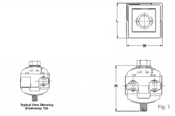
Connector, Piercing Tap 4/0 - 1/0 - 6AWG.
Connector, Piercing Tap 4/0 - 1/0 - 6AWG. image
Get Latest Price Request a quote
Quick Details
Product Details
Insulation piercing capability eliminates the need for insulation stripping
UL486B Listed, AL9CU Rated, for copper and aluminum conductor combinations up to 90°C, *600 Volt applications
Insulation piercing design for use on hot-line applications eliminates the need for taping
Easy snap-out tabs eases installation and protects connection from dirt and debris
Simple bolt-on connection for ease of installation
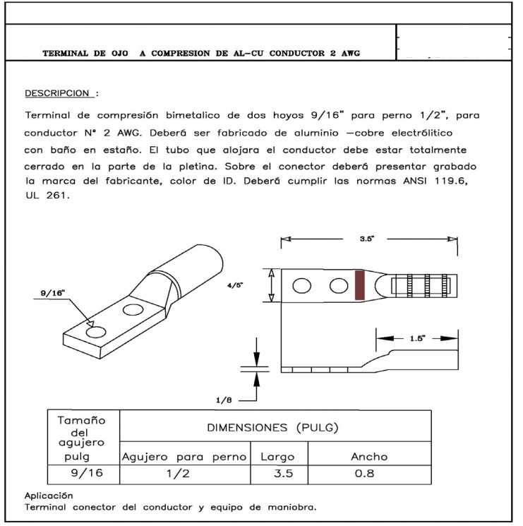
Terminal of Compression platen bimetallic p/conductor Nº2 (1 hole)
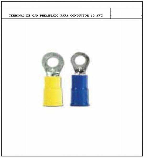
| Material name | Pre-insulated eye terminal for conductor 6mm ² No. 10 AWG | |
| Material | Must be made of bimetallic aluminum and copper material, covered with a tin layer with Vinyl insulation | |
| Finish | It must present a smooth surface, free of imperfections and defects | |
| Welding | By friction | |
| Rules | UL; CE and CSA | |
| Quality certificate | ISO 9001 | |
| DN-DS certificate | Attach certificate of acceptance and approval |
|
| Identification mark | The name of the manufacturer and the range of application must be engraved on the terminal | |
| Operating temperature | º C | 105 |
| Maximum voltage | v | 600 |
| Nominal size of the driver | AWG | #2 |
| Section of the internal conductor of the terminal | mm² | 6 |
| Driver | AWG | 10 |
| Identification mark | Each terminal must present a symbol or brand of manufacturing | |
| Packaging | The pre-insulated terminals should be packed in a highly resistant cardboard box identified with a label where it describes the No. 2 AWG gauge, manufacturer, quantity, country of origin |
Bimetallic Terminal of compression for driver N º 2 AWG (2 holes)
| Material name | Bimetallic Compression Terminal driver. No. 2 AWG- 2 hole |
|
| Material | º Must be made of material bimetallic terminal pads and connectors made of high conductivity copper and aluminum alloy coated with a tin layer, in order to increase its resistance to corrosion on the inside contain a structure and a compound that inhibits the galvanic couple, preventing corrosion and false contacts in the copper and aluminum joints. They have a bevel that facilitates the insertion of the driver and a full hole ensures that the connector or shoe is centered and perfectly sealed. For connections of terminals and splices up to 35 kv in aluminum cable. |
|
| Finish | It should present a smooth surface , free of imperfections and defects |
|
| Welding | By friction | |
| Rules | ANCI C119.4, IEEE 48-1996 | |
| Quality certificate | ISO 9001 | |
| Identification mark | The name of the manufacturer and the range of application must be engraved on the terminal | |
| Permissible driver 2 AWG | ACSR, AAC, AAAC, CU | |
| Nominal size of the driver | AWG | #2 |
| Diameter of the driver | mm | 7.417 |
| General Features | ||
| Internal diameter of drum |
inch(mm | 2/5 (10.12) |
| External diameter of drum |
inch(mm | 1/2 (13) |
| Holes | u | 2 |
| Identification color | Coffee | |
| Dimension | ||
| Diameter of the hole | inch(mm) | 9/16 (14.22) |
| Distance between holes | inch(mm) | ¾-1 (19.05 -25.4) |
| Approximate Length (L) | inch(mm) | 3.5 (89) |
| Approximate width (W) | inch(mm) | 4/5 (20) |
| Approximate thickness | inch(mm) | 0.12 (3.04) |
| Packaging | It should be packed in a box Highly resistant cardboard identified with a label where you describe caliber # 2 AWG, manufacturer, quantity, country of origin |
Terminal of Compression Bimetallic p/conductor N º 4/0 AWG
| Material name | Compression Connector Terminal Bimetallic terminal for driver No. 4/0 AWG |
|
| Material | It should be made of bimetallic aluminum and copper material, covered with a layer of tin, a In order to increase its resistance to corrosion. |
|
| Finish | It should present a smooth surface , free of imperfections and defects |
|
| Welding | By friction | |
| Rules | ANCI C119.4, IEEE 48-1996 | |
| Quality certificate | ISO 9001 | |
| Approval certificate | Attach certificate of acceptance of DN-DS |
|
| Permissible driver 3/0 | AWG | ACSR, AAC, AAAC, CU |
| Dimension | ||
| Nominal size of the driver |
AWG | No. 4/0 |
| Diameter of driver applying approximate | mm | 13.25 |
| Number of Holes | u | 2 |
| Identification color | Purple | |
| Dimension | ||
| Diameter of the hole | inch(mm) | 9/16 (14.29) |
| Distance between holes | inch(mm) | 1-3 / 4 (44.45) |
| Approximate length (L) | inch(mm) | 5.16 (131.1) |
| Width (W) | inch(mm) | 1 (25.4) |
| Thickness | inch(mm) | 0.18 (4.57) |
| Dialing | You must present the mark or symbol of the manufacturer |
|
| Packaging | It should be packed in a box Highly resistant cardboard identified with a label describing the caliber # 2 AWG, manufacturer, quantity, country of origin |
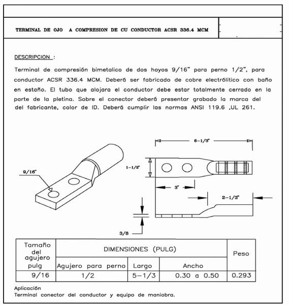
Terminal of Compression Bimetallic p/conductor N º 336.4 MCM
| Material name | Bimetallic Compression Terminal for driver No. 336.4 MCM. |
|
| Material | It should be made of material bimetallic terminal pads and connectors made of high conductivity copper and aluminum alloy coated with a tin layer, in order to increase its resistance to corrosion on the inside contain a structure and a compound that inhibits the galvanic couple, preventing corrosion and false contacts in the copper and aluminum joints. They have a bevel that facilitates the insertion of the driver and a full hole ensures that the connector or shoe is centered and perfectly sealed. For connections of terminals and splices up to 35 kv in aluminum cable. |
|
| Rules | ANSI C119.4, IEEE 48-1996 | |
| Quality certificate | ISO 9001 | |
| Approval certificate | Attach DN-DS certificate | |
| Finish | It should present a smooth surface , free of imperfections and defects |
|
| Welding | By friction | |
| Admitted drivers | ACSR, AA, AAAC | |
| Nominal size of the driver | 3356.4 MCM | |
| Diameter of the driver that applies | mm | 15.6 |
| Characteristics | ||
| Color code | Red | |
| Number of holes | u | 2 |
| Diameter of the hole | inch(mm) | 9/16 (14.28) |
| Bolt diameter | inch(mm) | ½ (12.7) |
| Dimension | ||
| Length between holes center | inch(mm) | 1-3 / 4 (44.5) |
| Identification mark | The terminals of the connectors they must be marked with the manufacturer’s symbol, catalog number, application conductor ranges and die number to occupy with the hydraulic tool for installation. When this information is not possible to be presented in the body of the connector, it will be printed on the connector bag, except for the brand and the name of the manufacturer, which must necessarily be indicated on the body of the connector. Additionally, they will present marks for their correct location and compression when they are installed |
|
| Packaging | It should be packed in a box Highly resistant cardboard identified with a label where you describe caliber # 2 AWG, manufacturer, quantity, country of origin |
|
Terminal of compression Bimetallic p/conductor N º 3/0
| 4 | Material name | Compression Connector Terminal Bimetallic terminal for driver No. 3/0 AWG |
|
| 5 | Material | It should be made of bimetallic aluminum and copper material, covered with a layer of tin, a In order to increase its resistance to corrosion. |
|
| 6 | Finish | It should present a smooth surface , free of imperfections and defects |
|
| 7 | Welding | By friction | |
| 8 | Rules | ANCI C119.4, IEEE 48-1996 | |
| 9 | Quality certificate | ISO 9001 | |
| 10 | Approval certificate | Attach certificate of acceptance of DN-DS |
|
| 11 | Permissible driver 3/0 | AWG | ACSR, AAC, AAAC, CU |
| 12 | Dimension | ||
| 13 | Nominal size of the driver |
AWG | No. 3/0 |
| Diameter of driver applying approximate | mm | 11.53 | |
| 14 | Number of Holes | u | 2 |
| 15 | Identification color | Orange | |
| Dimension | |||
| 16 | Diameter of the hole | inch(mm) | 9/16 (14.29) |
| 17 | Distance between holes | inch(mm) | 1-3 / 4 (44.45) |
| 18 | Approximate length (L) | inch(mm) | 3- 1/7 (80) |
| 19 | Width (W) | inch(mm) | Specify |
| 20 | Thickness | inch(mm) | 0.18 (4.57) |
| 21 | Dialing | You must present the mark or symbol of the manufacturer |
|
| 22 | Packaging | It should be packed in a box Highly resistant cardboard identified with a label describing the caliber # 2 AWG, manufacturer, quantity, country of origin |
bimetallic Terminal of compression for driver N º 2 AWG (2 holes)
| 4 | Material name | Bimetallic Compression Terminal driver. No. 1/0 AWG, two hole |
|
| 5 | Material | It should be made of material bimetallic aluminum and copper, coated with a layer of tin, in order to increase its resistance to corrosion. |
|
| 6 | Finish | It should present a smooth surface , free of imperfections and defects |
|
| 7 | Welding | By friction | |
| 8 | Rules | ANCI C119.4, IEEE 48-1996 | |
| 9 | Quality certificate | ISO 9001 | |
| 10 | Identification mark | The name of the manufacturer and the range of application must be engraved on the terminal | |
| 11 | Permissible driver 2 AWG | AWG | ACSR, AAC, AAAC, CU |
| 12 | Nominal size of the driver | AWG | # 1/0 |
| 13 | Driver’s diameter what applies |
mm | 9.14 |
| 14 | Holes | u | 2 |
| 15 | Identification color | pink | |
| Dimension | |||
| 16 | Diameter of the hole | inch(mm) | 9/16 (14.22) |
| 17 | Distance between holes | inch(mm) | 1-3 / 4 (44.45) |
| 18 | Approximate Length (L) | inch(mm) | 4.2 (106) |
| 19 | Approximate width (W) | inch(mm) | 4/5 (20) |
| 20 | Approximate thickness | inch(mm) | 0.18 (4.57) |
| 21 | Packaging | It should be packed in a box Highly resistant cardboard identified with a label where you describe caliber # 2 AWG, manufacturer, quantity, country of origin |
Splice full traction ACSR – AAAC No. 4/0 AWG
| 4 | Material name | Full traction joint for driver ACSR-AAAC No. 4/0 AWG |
|
| 5 | Splicing standards | ANSI C119.4, ASTM D 566 | |
| 6 | ISO Certificate | 9001 or recent | |
| 7 | Splice class | TO | |
| 8 | Raw material of the driver | Aluminium alloy | |
| 9 | Design of the splice to full traction | The tubular or cylindrical body made of aluminum, with holes in each of its ends, with the corresponding dimensions for the entry of the conductors for which they have been designed and with a stop inside, filled with inhibitor compound. |
|
| 10 | Splice fabrication | The joints must be designed with the materials of the best quality, allowing to fulfill their function without any problem, they must be stable and unalterable with time and the alloys used for their manufacture must not form galvanic couple that causes the degradation of the surfaces in contact, they must also guarantee the resistance to aggressive environments, chemical agents, humidity and any condition harmful to corrosion. |
|
| 11 | Calibers of drivers | mm | ACSR 4/0 |
| 12 | Diameter of the driver | mm | 14.3 |
| 13 | Sleeve length | mm | 420 |
| 14 | Central diameter of the splice | mm | 39 |
| 15 | Maximum tension | dAN | 3,787 |
| 16 | Color | Pink-Pink | |
| 17 | The splice nozzles must present | You must present a stopper on both ends sealant that prevents the entry of moisture and external agents into its interior that lead to corrosion of the same, similarly must fulfill the function of maintaining the inhibiting fat inside the splice during transport and storage |
|
| 18 | Identification Mark | You must submit a print on the body of the material name of the manufacturer, measure of conductor, tension, minimum pressure of the press |
|
| 19 | Packaging | The hose couplings of Full traction compression should be packed in a highly resistant cardboard box in order to protect in the transport and handling of the material |
Splice full traction ACSR-AAAC No. 1/0 to 1/0 AWG
| 4 | Material name | Full traction joint for driver ACSR-AAAC No. 1/0 to 1/0 AWG + |
|
| 5 | Splicing standards | ANSI C119.4, ASTM D 566 | |
| 6 | ISO Certificate | 9001 or recent | |
| 7 | Splice class | TO | |
| 8 | Raw material of the driver | Aluminium alloy | |
| 9 | Design of the splice to full traction | The tubular or cylindrical body made of aluminum, with holes in each of its ends, with the corresponding dimensions for the entry of the conductors for which they have been designed and with a stop inside, filled with inhibitor compound. |
|
| 10 | Splice fabrication | The joints must be designed with the materials of the best quality, allowing to fulfill their function without any problem, they must be stable and unalterable with time and the alloys used for their manufacture must not form galvanic couple that causes the degradation of the surfaces in contact, they must also guarantee the resistance to aggressive environments, chemical agents, humidity and any condition harmful to corrosion. |
|
| 11 | Calibers of drivers | mm | ACSR 1/0 |
| 12 | Diameter of the driver | mm | 10.12 |
| 13 | Sleeve length | mm | 300 to 330 |
| 14 | Central diameter of the splice | mm | 28 to 32 |
| 15 | Maximum tension | dAN | 1600 |
| 16 | Color | Yellow-yellow | |
| 17 | The splice nozzles must present | You must present a stopper on both ends sealant that prevents the entry of moisture and external agents into its interior that lead to corrosion of the same, similarly must fulfill the function of maintaining the inhibiting fat inside the splice during transport and storage |
|
| 18 | Identification Mark | You must present the engraving on the body of the material, name of the manufacturer, measure of the driver, tension, minimum pressure of the press |
Splice full traction ACSR-AAAC No. 2 to 2 AWG
Splice full traction ACSR MCM AWG No. 336.4 LINNET
Splice full traction ACSR-AAAC No. 4 AWG
| 4 | Material name | Full traction joint for driver ACSR -AAAC No. 2 to 2 AWG |
|
| 5 | Splicing standards | ANSI C119.4, ASTM D 566 | |
| 6 | ISO Certificate | 9001 or recent | |
| 7 | Splice class | TO | |
| 8 | Raw material of the driver | Aluminium alloy | |
| 9 | Design of the splice to full traction | The tubular or cylindrical body made of aluminum, with holes in each of its ends, with the corresponding dimensions for the entry of the conductors for which they have been designed and with a stop inside, filled with inhibitor compound. |
|
| 10 | Splice fabrication | The joints must be designed with the materials of the best quality, allowing to fulfill their function without any problem, they must be stable and unalterable with time and the alloys used for their manufacture must not form galvanic couple that causes the degradation of the surfaces in contact, they must also guarantee the resistance to aggressive environments, chemical agents, humidity and any condition harmful to corrosion. |
|
| 11 | Finish | The joint shall not present cracks, cavities, welds superficial or internal defects, or any other that may affect its correct functioning. |
|
| 12 | Calibers of drivers | ACSR 2 | |
| 13 | Diameter of the driver | mm | 8.05 |
| 14 | Splice length | mm | 300 to 320 |
| 15 | Central diameter of the splice | mm | 25 |
| 16 | Maximum tension | dAN | 1150 |
| 17 | Color | Red | |
| 18 | The splice nozzles must present | a sealing cap that prevents the entry of moisture and external agents into its interior that lead to corrosion of the same, similarly must fulfill the function of maintaining inhibitory fat inside the splice during transport and storage |
|
| 19 | DN-DS certificate | Attach acceptance certificate and homologation |
|
| 20 | Identification Mark | You must present the engraving on the body of the material, name of the manufacturer, measure of the driver, tension, minimum pressure of the press | |
| 21 | Packaging | Pre-insulated compression sleeve splices must be packed in a highly resistant cardboard box in order to protect in the transportation and handling of the material |
variety of connector products to fit most distribution applications. Installation methods may be automatic, bolted, or compression to connect various sizes and types of popular conductors (aluminum, copper, or bi-metallic) and support wires.
| 4 | Material name | Full traction joint for driver ACSR -AAAC Nº4 AWG |
|
| 5 | Splicing standards | ANSI C119.4, ASTM D 566 | |
| 6 | ISO Certificate | 9001 or recent | |
| 7 | DN-DS certificate | Attach certificate of acceptance and approval | |
| 8 | Splice class | TO | |
| 9 | Raw material of the driver | Aluminium alloy | |
| 10 | Design of the splice to full traction | The tubular or cylindrical body made of aluminum, with holes in each of its ends, with the corresponding dimensions for the entry of the conductors for which they have been designed and with a stop inside, filled with inhibitor compound. |
|
| 11 | Splice fabrication | The joints must be designed with the materials of the best quality, allowing to fulfill their function without any problem, they must be stable and unalterable with time and the alloys used for their manufacture must not form galvanic couple that causes the degradation of the surfaces in contact, they must also guarantee the resistance to aggressive environments, chemical agents, humidity and any condition harmful to corrosion. |
|
| 12 | Finish | The joint shall not present cracks, cavities, welds superficial or internal defects, or any other that may affect its correct functioning. |
|
| 13 | Calibers of drivers | ACSR 4 | |
| 14 | Diameter of the driver | mm | 5.80 to 6.45 |
| 15 | Splice length | mm | 260 |
| 16 | Central diameter of the splice | mm | 23 |
| 17 | Maximum tension | dAN | 1150 |
| 18 | Color | Orange | |
| 19 | The splice nozzles must present | a sealing cap that prevents the entry of moisture and external agents into its interior that lead to corrosion of the same, similarly must fulfill the function of maintaining inhibitory fat inside the splice during transport and storage |
|
| 20 | Identification Mark | You must present the engraving on the body of the material, name of the manufacturer, measure of the driver, tension, minimum pressure of the press | |
| 21 | Packaging | Pre-insulated compression sleeve splices must be packed in a highly resistant cardboard box in order to protect in the transportation and handling of the material |
Full pre-siled traction joint for driver No.
| 4 | Material name | Pre-insulated compression sleeve coupling 4/0 to 4/0 AWG | |
| 5 | Raw material of the driver | Tube or solid bar made of aluminum alloy | |
| 6 | Insulation material | Thermoplastic resistant to compression shall be such that it must guarantee the values of dielectric strength |
|
| 7 | Pre-insulated compression splice design | tubular or cylindrical body made of aluminum, with holes in each of its ends, with the corresponding dimensions for the entry of the conductors for which they have been designed and with a stop inside, filling a minimum of 20% of its capacity of neutral anti-humidity grease and to prevent its exit will be supplied properly plugged at both ends |
|
| 8 | Rules | ANSI C119.4, ASTM D 566 | |
| 9 | ISO Certificate | 9001 or recent | |
| 10 | Approval certificate | Attach the acceptance certificate DN-DS |
|
| 9 | Finish | The joints must be designed with the best quality materials, allowing to fulfill its function without any problem, they must be stable and unalterable with time and the alloys used for their manufacture must not form galvanic couple that causes the degradation of the surfaces in contact, they must also guarantee resistance to aggressive environments, chemical agents, humidity and any condition harmful to corrosion. The joint must not have cracks, cavities, welds superficial or internal defects, or any other that may affect its proper functioning. |
|
| 10 | Main range of driver input | AWG | 4/0 |
| 11 | Output range | AWG | 4/0 |
| 12 | Admissible section | mm² | 107.2 |
| 13 | Approximate length | inch(mm) | 5-1 / 2 (139.7) |
| 14 | Approximate maximum diameter of the sleeve | inch(mm) | 0.564 (14.32) |
| 15 | Approximate minimum diameter of the sleeve | inch(mm) | 0.522 (13.25) |
| 16 | Maximum tension | daN | 2,940 |
| 17 | Color A-B | Pink-Pink | |
| 18 | Identification Mark | Each splice must present the engraving on the body, name of the manufacturer, country of origin, range of driver, tension. |
|
| 19 | Packaging | The hose couplings of Pre-insulated compression should be packed in a highly resistant cardboard box in order to protect in the transport and handling of the material |
2
| Specify code and attach technical catalog of the model proposed by the manufacturer | |
| Full pre-siled traction joint for driver No. 2 |
|
| Tube or solid bar aluminium alloy |
|
| Compressive thermoplastic will be such that it must guarantee the values of the Dielectric strength |
|
| The tubular or cylindrical body manufactured in aluminum, with holes in each of its ends, with the corresponding dimensions for the entry of the conductors for which they were designed and with a stop inside, filling a minimum of 20% of its capacity of neutral anti-humidity grease and in order to avoid its exit, it will be properly sealed at both ends |
|
| ANSI C119.4, ASTM D 566 | |
| The joints must be designed with the best quality materials, allowing to fulfill its function without any problem, they must be stable and unalterable with time and the alloys used for their manufacture must not form galvanic couple that causes the degradation of the surfaces in contact, they must also guarantee resistance to aggressive environments, chemical agents, humidity and any condition harmful to corrosion. The joint must not have cracks, cavities, welds superficial or internal defects, or any other that may affect its proper functioning. |
|
| mm | AAAC 2 AL 2 |
| mm² | 33.62 |
| inch(mm) | 3-15 / 16 (100) |
| inch(mm) | 4/5 (20 |
| daN | 1,100 |
| Red Red | |
| You must present engraving on the body name of the manufacturer, measure of Driver, tension, | |
| The connectors must be packed in a highly resistant cardboard box for your transport, storage and handling |
| 4 | Material name | Full traction joint for driver ACSR-AAAC No. 3/0 AWG |
|
| 5 | Splicing standards | ANSI C119.4, ASTM D 566 | |
| 6 | ISO Certificate | 9001 or recent | |
| 7 | Splice class | TO | |
| 8 | Raw material of the driver | Aluminium alloy | |
| 9 | Design of the splice to full traction | The tubular or cylindrical body made of aluminum, with holes in each of its ends, with the corresponding dimensions for the entry of the conductors for which they have been designed and with a stop inside, filled with inhibitor compound. |
|
| 10 | Splice fabrication | The joints must be designed with the materials of the best quality, allowing to fulfill their function without any problem, they must be stable and unalterable with time and the alloys used for their manufacture must not form galvanic couple that causes the degradation of the surfaces in contact, they must also guarantee the resistance to aggressive environments, chemical agents, humidity and any condition harmful to corrosion. |
|
| 11 | Calibers of drivers | mm | ACSR 3/0 |
| 12 | Diameter of the driver | mm | 12.75 |
| 13 | Sleeve length | mm | 380 to 410 |
| 14 | Central diameter of the splice | mm | 36 to 40 |
| 15 | Maximum tension | dAN | 2,940 |
| 16 | Color | Pink- black | |
| 17 | The splice nozzles must present | You must present a stopper on both ends sealant that prevents the entry of moisture and external agents into its interior that lead to corrosion of the same, similarly must fulfill the function of maintaining the inhibiting fat inside the splice during transport and storage |
|
| 18 | Identification Mark | You must submit a print on the body of the material name of the manufacturer, measure of conductor, tension, minimum pressure of the press |
|
| 19 | Packaging | The hose couplings of Full traction compression should be packed in a highly resistant cardboard box in order to protect in the transport and handling of the material |
| 8 | Rules | ANCI C119.4, IEEE 48-1996 | |
| 9 | Quality certificate | ISO 9001 | |
| 10 | Approval certificate | Attach certificate of acceptance of DN-DS |
|
| 11 | Permissible driver 3/0 | AWG | ACSR, AAC, AAAC, CU |
| 12 | Dimension | ||
| 13 | Nominal size of the driver |
AWG | No. 3/0 |
| Diameter of driver applying approximate | mm | 11.53 | |
| 14 | Number of Holes | u | 2 |
| 15 | Identification color | Orange | |
| Dimension | |||
| 16 | Diameter of the hole | inch(mm) | 9/16 (14.29) |
| 17 | Distance between holes | inch(mm) | 1-3 / 4 (44.45) |
| 18 | Approximate length (L) | inch(mm) | 3- 1/7 (80) |
| 19 | Width (W) | inch(mm) | Specify |
| 20 | Thickness | inch(mm) | 0.18 (4.57) |
| 21 | Dialing | You must present the mark or symbol of the manufacturer |
|
| 22 | Packaging | It should be packed in a box Highly resistant cardboard identified with a label describing the caliber # 2 AWG, manufacturer, quantity, country of origin |
| Product | Tension Clamp 100-150mm Square | ||||||
| Test Items | Test Content | Test Result | |||||
| Sample 1 |
Sample 2 |
Sample 3 |
Sample 4 |
Sample 5 |
Remarks | ||
| Visual Inspection | Crack | √ | √ | √ | √ | √ | 1) Passed Mark"√" 2) Not Passed Mark"×" Test Conclusion: |
| Stoma Trachoma | √ | √ | √ | √ | √ | ||
| Fins | √ | √ | √ | √ | √ | ||
| Burr | √ | √ | √ | √ | √ | ||
| Mechanical Characteristics | Mechanical Load | √ | √ | √ | √ | √ | 1)Passed Mark"√" 2)Not Passed Mark"×" Test Conclusion: |
| Inspector | Date: 18. June,2010 Approved: | ||||||
| S/N | DETAILS | UNITS | DATA |
| 1. | Type | 100mm2 Compression type mid span joint complete with a tubular aluminium outer extrusion ,steel inner sleeve and two filler plugs |
|
| 2. | Material for outer extrusion |
Aluminium -99.5% purity | |
| 3. | Material for inner sleeve | HDG steel | |
| 4. | Type of inner sleeve | Tubular, suitable for compression into hexagonal shape |
|
| 5. | Suitable for the following ACSR Conductor Size |
mm2 | 100 |
| 6. | Resistivity | Less than 75% of the resistivity of an equivalent length of conductor. |
|
| 7. | Minimum failing load | kN | 35 |
| 8. | Operating ambient temperature |
°C | -1 to 40 |
| 9. | Relative Humidity | % | 85 |
| 10. | Altitude above sea level | m | 1400 |
CLAMP P/G ALUMINIUM/ALUMINIUM 100/100 MM2
| S/N | TYPE | CONDUCTOR CROSS SECTION AREAS (mm2) |
NUMBER AND MATERIAL OF BOLT |
CLAMP BODY MATERIAL |
DIMENSI ONS |
| 1. | Aluminium/Aluminiu m conductor connection |
100/100 | 2 X Galvanised mild steel bolts |
Aluminium | As per Drawing No.E11389 shown below |
| Other dimensions | |||||
| 2. | Drawings showing dimensions to be provided with bid |
Yes/No | Yes | ||
| 3. | Previous type tests results/certificate to be provided with bid |
Yes/No | Yes | ||
| 4. | Quality assurance certificate to be provided with bid |
Yes/No | Yes | ||
| 5. | Applicable standard | IEC standards | |||
| 4 | Material name | Full traction joint for driver ACSR MCM No. 336.4 AWG LINNET |
|
| 5 | Splicing standards | ANSI C119.4, ASTM D 566 | |
| 6 | ISO Certificate | 9001 or recent | |
| 7 | Splice class | TO | |
| 8 | Raw material of the driver | Aluminium alloy | |
| 9 | Design of the splice to full traction | The tubular or cylindrical body made of aluminum, with holes in each of its ends, with the corresponding dimensions for the entry of the conductors for which they have been designed and with a stop inside, filled with inhibitor compound. |
|
| 10 | Splice fabrication | The joints must be designed with the materials of the best quality, allowing to fulfill their function without any problem, they must be stable and unalterable with time and the alloys used for their manufacture must not form galvanic couple that causes the degradation of the surfaces in contact, they must also guarantee the resistance to aggressive environments, chemical agents, humidity and any condition harmful to corrosion. |
|
| 11 | Calibers of drivers | mm | ACSR MCM 336.4 AWG |
| 12 | Diameter of the driver | mm | 19.39 a 18 |
| 13 | Sleeve length | mm | 530 |
| 14 | Central diameter of the splice | mm | 48 |
| 15 | Maximum tension | dAN | 5,000 |
| 16 | Color Of plugs | green | |
| 17 | The splice nozzles must present | You must present a stopper on both ends sealant that prevents the entry of moisture and external agents into its interior that lead to corrosion of the same, similarly must fulfill the function of maintaining the inhibiting fat inside the splice during transport and storage |
|
| 18 | Identification Mark | You must submit a print on the body of the material name of the manufacturer, measure of conductor, tension, minimum pressure of the press |
|
| 19 | Packaging | The hose couplings of Full traction compression should be packed in a highly resistant cardboard box in order to protect in the transport and handling of the material |
Recommended for You
Not exactly what you want?
Post Sourcing Request
Hot Searches
Cable Terminal
Power Terminal
Wire Terminal
Power Cable Accessories
Terminal Connector
We are China Connector, Piercing Tap 4/0 - 1/0 - 6AWG. manufacture and supplier,You can get more details with Email,you will get cheap price or factory price.
Get Latest Price Request a quote
Popular Bimetallic Terminal Products
Bimetallic Terminal of Compression for Driver N º 2 AWG (2 holes)
Terminal of Compression Platen Bimetallic P/Conductor Nº 2 (1 hole)
Terminal of Compression Bimetallic P/Conductor N º 3/0
Terminal of Compression Bimetallic P/Conductor N º 4/0 AWG
Bimetallic Terminal of Compression for Driver N º 2 AWG (2 holes)
Terminal of Eye Conductive Preaislado PARA 6 mm ² , 10 AWG
Popular Cable Lug Products
Copper Terminal Earthing Cable Lug
High Quality Bimetal Terminal Cable Connectors Lug
Furcate Pre-Insulating Spade Terminal
Gty Copper Connecting Pipe Cable Lug
New Product Manufactured Gtl Bimetal Types Cable Connector Link Cable Sleeve Cable Ferrul
Cable Lug Tinned Copper Cable Lug for Cable Connection Dt10-6
Popular jgtrade1 Products
12kv Surge Arrester Outdoor Vertical Operate Semi Pantograph Type Isolator Switch 3 Phase
25kv Polymer Strain Insulators
Dimensions, Packaging and Marking
Surge Arrester Distribution 11kv
Popular Terminal Lug Products
Dtl-2 a Type Terminal Connector Copper Aluminium Crimp Terminal Metal Lug
Terminal of Compression Bimetallic P/Conductor N º 336.4 Mcm
Al-Cu Dtl-2 Bimetal Cable Lug Cable Terminal Aluminium Copper Electric Power Fittings
Copper Tube Sc Terminals Non-Insulated Cable Lug Connectors Terminals Copper Lug
Compression Cable Lugs Termination Connector Terminal Tin Plated Dt Type Copper Lug
Gty Series Copper Connecting Tube for Wire
Tags: Bimetallic Terminal, Cable Lug, jgtrade1, Terminal LugSimilar Or Related
-

Bimetallic Terminal of Compression for Driver N º 2 AWG (4 holes)
-
Terminal of Compression Bimetallic P/Conductor N º 336.4 Mcm
-
Terminal of Compression Bimetallic P/Conductor N º 3/0
-
Terminal of Eye Conductive Preaislado PARA 6 mm ² , 10 AWG
-
Bimetallic Terminal of Compression for Driver N º 2 AWG (2 holes)


If you have any questions or would like to book a session please contact us.