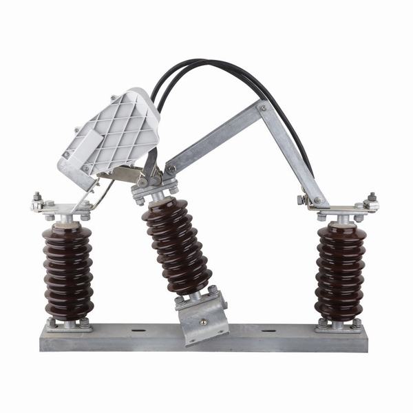
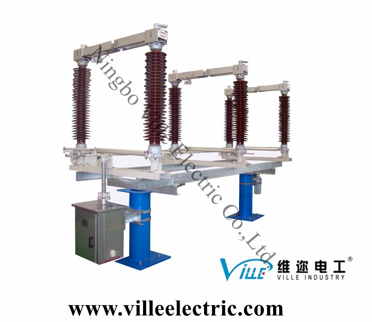
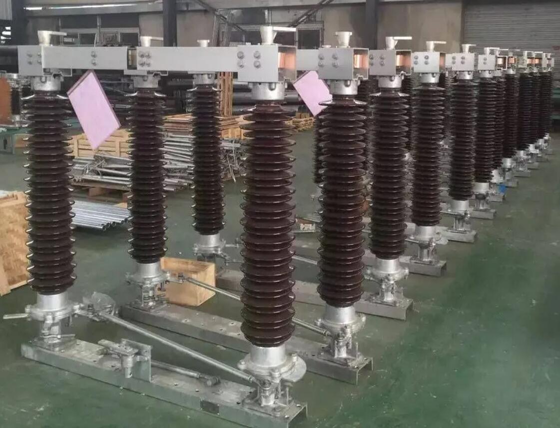
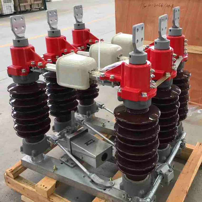
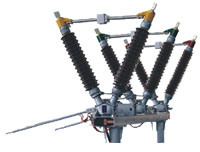
Isolator, Gang Operated
Isolator, Gang Operated image
Get Latest Price Request a quote
Quick Details
Product Details
Center Break Isolator and double Break Isolator
The following documents were referred to during the preparation of this specification. In case of conflict, the provisions of this specification shall take precedence.
IEC 129:1975: Alternating Current Disconnectors (Isolators) and Earthing Switches
IEC 60694:2002: Common Specifications for High Voltage Switchgear and Controlgear
BS 729: Hot dip galvanized coating on iron and steel articles
IEC62271-102
Isolator (Disconnector) – a mechanical switching device which provides, in the open position, an isolating distance in accordance with Electrical Safety requirements.
SERVICE CONDITIONS
The isolator shall be suitable for continuous operation outdoors in tropical areas at altitudes of up to 2200m above sea level, humidities of up to 90%, average ambient temperature of +30ºC with a minimum of -1ºC and a maximum of +40ºC and heavy saline conditions along the coast.
4.2. DESIGN AND CONSTRUCTION
4.2.1 The Isolator, Solid Link shall be designed and constructed in accordance with IEC 129 and IEC 60694.
4.2.2 The isolating link shall be of the vertical opening, designed for single phase manual operation. It shall be easily removed and replaced by using a portable operating rod.
4.2.3 The isolating link shall incorporate double porcelain insulators to suit voltage requirements and mounted on hot dipped galvanised steel under base suitable for vertical mounting.
4.2.4 The isolating link shall be arranged so that each unit is mounted independently on an angle bracket. It shall be supplied complete with the angle bracket and accessories suitable for mounting on ‘U’ type steel channel. The drawings to be submitted shall indicate all the applicable mounting positions.
4.2.5 The isolator shall be designed such that in fully open position, it shall provide adequate electrical isolation between the contacts on each phase. It shall conform to the requirement as single point isolation for safety.
4.2.6 All steel parts shall be hot dip galvanized to BS 729. The minimum coating of galvanizing required is 80 microns.
4.2.7 The solid link shall be removable from the mounting by use of operating rod.
4.2.8 All current carrying parts of the isolator shall be made of high conductivity material.
4.2.9 The isolator shall be fitted with clamp connectors for Aluminium (ACSR) conductor of Aluminium (ACSR)conductor of up to 18.2mm diameter.
The rating of the complete isolator shall be as follows: –
Rated voltage
36 kV
Rated frequency
50 Hz
Rated lightning impulse withstand voltage
200 kV
Rated power frequency withstand voltage, dry
95 kV
Rated normal current
400 Amps
Rated short time withstand current for 3 sec, min.
18.0 kA
Minimum creepage distance of insulators
900 mm
| N/O | DETAIL | DATA | ||
| 1 | Description | Solid link assembly complete with link rated at 200A and mounting bracket to PIESA 002. (See Figure 1 to Figure 12 below) |
||
| 2 | System conditions of service a) nominal Voltage (Un) r.m.s |
kV |
11 |
|
| b) maximum system voltage (Um) r.m.s | KV | 12 | ||
| c) earthing | Effective & non effective | |||
| d) Frequency | Hz | 50 | ||
| 3 | Site conditions of service a) altitude |
m |
1400 |
|
| b) Operating Ambient temperature | °C | –1 to 40 | ||
| c) Humidity | % | 85 | ||
| 4 | Rating | |||
| a) Nominal voltage | kV | 11 | ||
| b) Rated current | Solid link | A |
200 |
|
| Cut out base |
A |
200 |
||
| 5 | Electrical components | |||
| a) Insulator material specification | Porcelain | |||
| Dielectric strength | ||||
| Lightning impulse withstand (1.2/50) | kV | 95 | ||
| Power frequency wet withstand voltage r.m.s |
kV | 28 | ||
| 6 | Specific creepage distance | mm/kV | 25 | |
| 7 | General information to be provided with bid: Drawings and brochures showing outline and general arrangement |
Yes/No |
Yes |
| b) Detailed drawings of all items showing critical tolerances to be provided with bid |
Yes/No | Yes | |
| 8 | Previous Type test report/certificate on complete solid link assembly to be provided with bid |
Yes/No |
Yes |
| 10 | Routine tests (acceptance tests on sample Product) to be provided on delivery |
Yes/No | Yes |
| 11 | Applicable standard | PIESA 002 | |
| 12 | Other applicable standards | NRS 035 SABS IEC 60282–2 SABS IEC 60186 BS 137 part 2 |
TRI–LINKS
Lot 3–(a) 11kV with interrupters
| N/O | DETAIL | DATA | |
| 1 | TYPE | 11kV pre-assembled gang operated overhead line load break switch complete with expulsion interrupters |
|
| 2 | Mounting configuration | Horizontal | |
| 3 | Mode of operation | Manually operated pole mounted linking rod and handle with locking facilities |
|
| a) nominal Voltage (Un) r.m.s | kV | 11 | |
| b) maximum voltage (Um) r.m.s | KV | 12 | |
| c) earthing | Effective & non effective | ||
| d) Frequency | Hz | 50 | |
| e) rated current | Amp | 400 | |
| f) Fault closing capacity | kA | 12.5 | |
| 4 | Site conditions of service a) altitude |
metres |
1400 |
| b) Operating Ambient temperature | °C |
–1 to +40 |
|
| c) Relative humidity | % | 85 | |
| 5 | Electrical components | ||
| a) Insulator material specification | High Temperature Vulcanised Silicon rubber |
||
| b) Cross arm and operating controls materials | Hot dip galvanized steel to SAN760 |
||
| Dielectric strength | |||
| Lightning impulse withstand (1.2/50) | kV | 95 |
| Power frequency wet withstand voltage r.m.s | KV | 28 | |
| Short time current rating –1sec | kA | 12.5 | |
| 6 | creepage distance | mm/kV | 25 |
| 7 | General information to be provided with bid: Drawings and brochures showing Outline and general arrangement |
Yes/No |
Yes |
| 8 | Previous Type test report/certificate on complete assembly to be provided with bid |
Yes/No | Yes. |
| 9 | Routine tests (acceptance tests on sample Product) to be provided on delivery. |
Yes/No | Yes |
| 10 | Applicable standards | IEC62271 |
FURTHER REQUIREMENTS:
Water shall not be able to accumulate on any part of the equipment nor shall any feature introduce moisture into any component.
The design shall incorporate all reasonable precautions and provisions for the safety of personnel concerned with the operation and maintenance of the same.
The current path shall be such that load current shall only flow through high conductive materials such as copper and its alloys. Load current shall not be permitted to flow through ferrous components, springs, or spring–loaded mechanisms.
All load current paths shall be so designed that the relevant parts of the switch are capable of carrying the specified rated current without exceeding the permitted temperature rise.
SUPPLIMENTARY NOTES
Suppliers should give sufficient information including drawings (which must be brief, clear and to the point) on how their switch designs addresses these requirements. Further, Suppliers may offer better alternatives that are of cost benefits to customer, It is therefore imperative that schedule "B" is completed by the tenderer. Any deviations/modifications/alternatives specification must be listed in schedule "C.
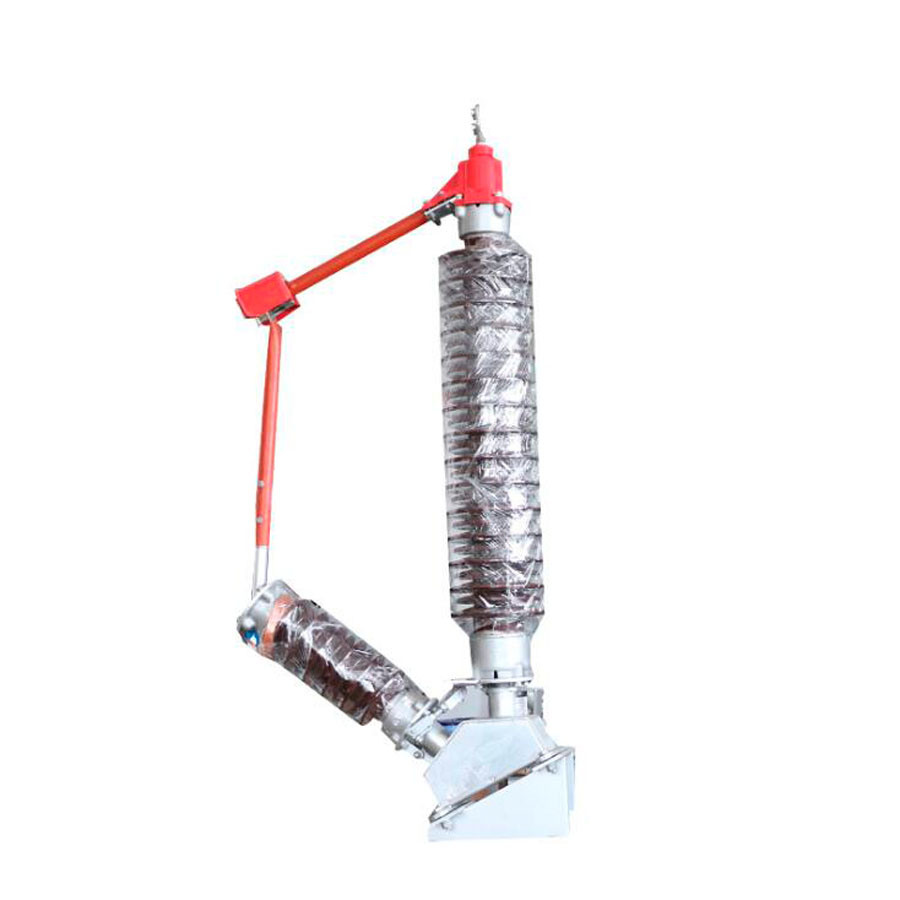
33kV with interrupters
| N/O | DETAIL | DATA | |
| 1 | TYPE | 33kV pre-assembled gang operated overhead line load break switch complete with expulsion interrupters |
|
| 2 | Mounting configuration | Horizontal | |
| 3 | Mode of operation | Manually operated pole mounted linking rod and handle with locking facilities |
|
| a) nominal Voltage (Un) r.m.s | kV | 33 | |
| b) maximum voltage (Um) r.m.s | KV | 36 | |
| c) earthing | Effective & non effective | ||
| d) Frequency | Hz | 50 | |
| e) rated current | Amp | 200 | |
| f) Fault closing capacity | kA | 12.5 | |
| 4 | Site conditions of service a) altitude |
metres |
1400 |
| b) Operating Ambient temperature | °C |
–1 to +40 |
|
| c) Relative humidity | % | 85 | |
| 5 | Electrical components | ||
| a) Insulator material specification | High Temperature Vulcanised Silicon rubber |
||
| b) Cross arm and operating controls materials | Hot dip galvanized steel to SAN760 |
||
| Dielectric strength | |||
| Lightning impulse withstand (1.2/50) | kV | 170 | |
| Power frequency wet withstand voltage r.m.s | KV | 70 | |
| Short time current rating –1sec | kA | 12.5 | |
| 6 | creepage distance | mm/kV | 25 |
| 7 | General information to be provided with bid: |
| Drawings and brochures showing Outline and general arrangement |
Yes/No |
Yes |
|
| 8 | Previous Type test report/certificate on complete assembly to be provided with bid |
Yes/No | Yes |
| 9 | Routine tests (acceptance tests on sample Product) to be provided on delivery |
Yes/No | Yes |
| 10 | Applicable standards | IEC62271 |
FURTHER REQUIREMENTS:
Water shall not be able to accumulate on any part of the equipment nor shall any feature introduce moisture into any component.
The design shall incorporate all reasonable precautions and provisions for the safety of personnel concerned with the operation and maintenance of the same.
The current path shall be such that load current shall only flow through high conductive materials such as copper and its alloys. Load current shall not be permitted to flow through ferrous components, springs, or spring–loaded mechanisms.
All load current paths shall be so designed that the relevant parts of the switch are capable of carrying the specified rated current without exceeding the permitted temperature rise.
SUPPLIMENTARY NOTES
Suppliers should give sufficient information including drawings (which must be brief, clear and to the point) on how their switch designs addresses these requirements. Further, Suppliers may offer better alternatives that are of cost benefits to custoemr.
11kV without interrupters
| N/O | DETAIL | DATA | |
| 1 | TYPE | 11kV pre-assembled gang operated overhead line switch without expulsion interrupters (non–load break switch) |
|
| 2 | Mounting configuration | Horizontal | |
| 3 | Mode of operation | Manually operated pole mounted linking rod and handle with locking facilities |
|
| a) nominal Voltage (Un) r.m.s | kV | 11 | |
| b) maximum voltage (Um) r.m.s | KV | 12 | |
| c) earthing | Effective & non effective | ||
| d) Frequency | Hz | 50 | |
| e) rated current | Amp | 400 | |
| 4 | Site conditions of service a) altitude |
metres |
1400 |
| b) Operating Ambient temperature | °C |
–1 to +40 |
|
| c) Relative humidity | % | 85 | |
| 5 | Electrical components | ||
| a) Insulator material specification | High Temperature Vulcanised Silicon rubber |
||
| b) Cross arm and operating controls materials | Hot dip galvanized steel to SAN760 |
||
| Dielectric strength | |||
| Lightning impulse withstand (1.2/50) | kV | 95 | |
| Power frequency wet withstand voltage r.m.s | KV | 28 | |
| Short time current rating –1sec | kA | 12.5 | |
| 6 | creepage distance | mm/kV | 25 |
| 7 | General information to be provided with bid: |
| Drawing and brochures showing Outline and general arrangement |
Yes/No |
Yes |
|
| 8 | Previous Type test report/certificate on complete assembly to be provided with bid |
Yes/No | Yes |
| 9 | Routine tests (acceptance tests on sample Product) to be provided on delivery |
Yes/No | Yes |
| 10 | Applicable standards | IEC62271 |
FURTHER REQUIREMENTS:
Water shall not be able to accumulate on any part of the equipment nor shall any feature introduce moisture into any component.
The design shall incorporate all reasonable precautions and provisions for the safety of personnel concerned with the operation and maintenance of the same.
The current path shall be such that load current shall only flow through high conductive materials such as copper and its alloys. Load current shall not be permitted to flow through ferrous components, springs, or spring–loaded mechanisms.
All load current paths shall be so designed that the relevant parts of the switch are capable of carrying the specified rated current without exceeding the permitted temperature rise.
SUPPLIMENTARY NOTES
Suppliers should give sufficient information including drawings (which must be brief, clear and to the point) on how their switch designs addresses these requirements. Further, Suppliers may offer better alternatives that are of cost benefits to
33kV without interrupters
| N/O | DETAIL | DATA | |
| 1 | TYPE | 33kV pre-assembled gang operated overhead line switch without expulsion interrupters (non–load break switch) |
|
| 2 | Mounting configuration | Horizontal | |
| 3 | Mode of operation | Manually operated pole mounted linking rod and handle with locking facilities |
|
| a) nominal Voltage (Un) r.m.s | kV | 33 | |
| b) maximum voltage (Um) r.m.s | KV | 36 | |
| c) earthing | Effective & non effective | ||
| d) Frequency | Hz | 50 | |
| e) rated current | Amp | 200 | |
| 4 | Site conditions of service a) altitude |
metres |
1400 |
| b) Operating Ambient temperature | °C |
–1 to +40 |
|
| c) Relative humidity | % | 85 | |
| 5 | Electrical components | ||
| a) Insulator material specification | High Temperature Vulcanised Silicon rubber |
||
| b) Cross arm and operating controls materials | Hot dip galvanized steel to SAN760 |
||
| Dielectric strength | |||
| Lightning impulse withstand (1.2/50) | kV | 170 | |
| Power frequency wet withstand voltage r.m.s | KV | 70 | |
| Short time current rating –1sec | kA | 12.5 | |
| 6 | creepage distance | mm/kV | 25 |
| 7 | General information to be provided with bid: |
| Drawing and brochures showing Outline and general arrangement |
Yes/No |
Yes |
|
| 8 | Previous Type test report/certificate on complete assembly to be provided with bid |
Yes/No | Yes |
| 9 | Routine tests (acceptance tests on sample Product) to be provided on delivery |
Yes/No | Yes |
| 10 | Applicable standards | IEC62271 |
FURTHER REQUIREMENTS:
Water shall not be able to accumulate on any part of the equipment nor shall any feature introduce moisture into any component.
The design shall incorporate all reasonable precautions and provisions for the safety of personnel concerned with the operation and maintenance of the same.
The current path shall be such that load current shall only flow through high conductive materials such as copper and its alloys. Load current shall not be permitted to flow through ferrous components, springs, or spring–loaded mechanisms.
All load current paths shall be so designed that the relevant parts of the switch are capable of carrying the specified rated current without exceeding the permitted temperature rise.
SUPPLIMENTARY NOTES
Suppliers should give sufficient information including drawings (which must be brief, clear and to the point) on how their switch designs addresses these requirements. Further, Suppliers may offer better alternatives that are of cost benefits to.
We are China Isolator, Gang Operated manufacture and supplier,You can get more details with Email,you will get cheap price or factory price.
Get Latest Price Request a quote
Popular Disconnect Switch Products
Gw90 Series Hv Outdoor High Voltage Disconnect /Switch Isolator Disconnect Switch / Isolator Switch
35 Isolator Switch 3 Phase Waterproof Disconnect Isolating Switch
T-Connectors for Two Bundle Conductor & single Tap Conductor Type Tl
Low Loss Switchboard, Electric Switch, 27.5V Outdoor Air Insulated Switchgear for Power Grid/ Subway
High -Voltage Isolate Switch 17.5kv
11kv, 33kv Disconnect Switch Isolation Switch Withpolymeric Insulator Factory Price
Popular Disconnector Products
75kv Gw4 Outdoor Hv Disconnector/Disconnecting Switch
Outdoor AC High Voltage Disconnector Model (GW4)
110kv Outdoor Hv Sf6 Gas Live Tank Disconnector Circuit Breaker
Outdoor off Load Disconnect Switch
Gw9 Series 12kv Outdoor High Voltage Disconnect Switch Hv
Popular Isolator Switch Products
15kv Single Pole Combination by-Pass and Disconnect Switch
75kv Outdoor High Voltage Three Phase Isolator Disconnector Switch
33kv Isolator Current 2000A Without Earth Switch
High -Voltage Isolate Switch 24kv 200A
China Manufacturer Power Electric polymer Isolator Switch
High -Voltage Isolate Switch 12kv 600A
Popular jgtrade1 Products
35kv Polymer Strain Insulators
33 Kv off-Load Isolator Without Earth Blade
Overload Protection High Voltage Expulsion Porcelain 11kv Drop-out Fuse Cutout
Tags: Disconnect Switch, Disconnector, Isolator Switch, jgtrade1Similar Or Related
-

Gw4a 72.5 Isolator Disconnector Isolation Switch 363kv
-
Gw4-40.5 Disconnector Outdoor AC Hv Disconnector
-
Gw4-10.5 Series Outdoor AC High-Voltage Disconnecting Switch
-
Gw5-10.5 Series Outdoor AC High-Voltage Disconnecting Switch
-
Gw13-110/630 110kv Outdoor High Voltage Disconnector, Disconnecting Switch
If you have any questions or would like to book a session please contact us.