Lug, 2 Hole 4/0

Lug, 2 Hole 4/0 image
Get Latest Price Request a quote
Quick Details
Product Details
Connectors must be clearly marked with wire size, die index, color code, and crimp location bands
Must pre-filled with oxide inhibitor
Must have color coded end caps are factory inserted in the barrels to match the die
color code and prevent foreign materials from entering the barrel.
Must accommodate conductor types:
o Aluminum Code Wire: Class B (Concentric, Compressed, Compact)
o Copper Code Wire: Class B (Concentric, Compressed, Compact or Class C
o Copper Clad Aluminum: Noted in the conductor accommodates as CCA
STANDARDS
The Load Isolator and Expulsion Fusegear shall comply with the latest edition of and amendments to the Standards/Specifications listed below:
IEC International Electrotechnical Commission
IEC 60060 – High Voltage Test Techniques
IEC 60129 – Alternating Current disconnectors and Earth Switches
IEC 602822 – High Voltage fuses. parts 2: Expulsion and similar fuses
IEC 60383 – Tests on insulators of ceramic material or glass for overhead lines with a nominal voltage greater than 1000V
IEC 60437 – Radio Interference test on high voltage insulators
IEC 60507 – Artificial pollution tests on high voltage insulators to be used on A.C. systems.
IEC 60694 – Common specification for high voltage switchgear and control gear standards.
NEMA National Electrical Manufacturers Association
NEMA SG2 – High Voltage fuses.
ANSI – American national Standards Institute
IEEE C37.41 – Design tests for high voltage fuses, distribution enclosed single pole switches, fuse disconnecting switches and accessories.
ANSI C37.42 – American national Standard Specifications for Distribution Cutouts and Fuse Links.
Associated Sections/Specifications
A. Routine Tests
Routine Tests for load Isolators shall be carried out in accordance with IEC 60129. Routine tests for Expulsion Fusegear shall be selected from the type tests in accordance with IEC 60282, Clause 8.
B. Type Tests
1. Type Tests shall be carried out on individual units at Purchaser’s request and shall be separately priced. Any particular unit or units may, at Purchaser’s option, be chosen for testing.
Type/Design Tests may (at the Purchaser’s discretion) be dispensed with if the Supplier furnishes evidence to the Purchaser’s satisfaction that the relevant tests have already been performed on identical equipment. In this case the Supplier shall provide documentary proof in the form of Certified Test Certificates that the assembled equipment and its component parts been successfully typetested by an independent testing authority in accordance with the relevant clauses of referenced Standards. Test Certificates as evidence of successful completion of type tests shall be submitted as part of the Bid.
Acceptable independent testing Authorities include the following: KEMA – Holland, CESI – Italy, EDF – France and IREQ, – Quebec, Canada. Approval of type tests certificates supplied by any other authority is subject to the written acceptance of the Electricity Company of Ghana.
The supplier shall confirm on the attached schedule that the following tests have been performed according to IEC 60129, IEC60060, IEC 60437, IEC 602822 and IEC 60507.
a. Dielectric Test on Expulsion Fusegear and Load Isolator
b. Interrupting tests; Load Isolator only
c. Radio Interference test on Expulsion Fusegear and Load Isolator
d. Short time current on load isolator only
e. A temperature rise test is required for expulsion fusegear and load isolators per IEC 60060.
f. Operating and mechanical endurance tests for IEC 60129
g. Operation at the temperature limits to IEC 60129.
h. Load Break Tests to IEEE C37.41
2. Where load break or making current tests have been performed on the model being offered, these test results shall also be attached
3. Corrosion Performance tests
Salt spray corrosion performance after 1000 hours according to IEC 60507 or equivalent field experience in coastal sites.
The manufacturer shall confirm that the current contacts shall meet the temperature rise requirements after approx. 20 coastal exposures and that all other metal parts shall retain their mechanical strengths.
2.01 DESIGN LOAD ISOLATORS
The complete assemblies shall be rated 105oC for normal circuit conditions as per IEC 60129. They shall also meet the following electrical test requirements.
A. Performance Characteristics
1. Voltage
a. BIL: 75kV, 1.2 x 50 microsecond wave.
b. A.C. Withstand: 28kV, 50Hz, 1 minute; dry and wet.
2. Current
a. Continuous Operation and Load interrupting: 100A, 200A, 400A
b. Shorttime: 12,500 amps RMS 1 second
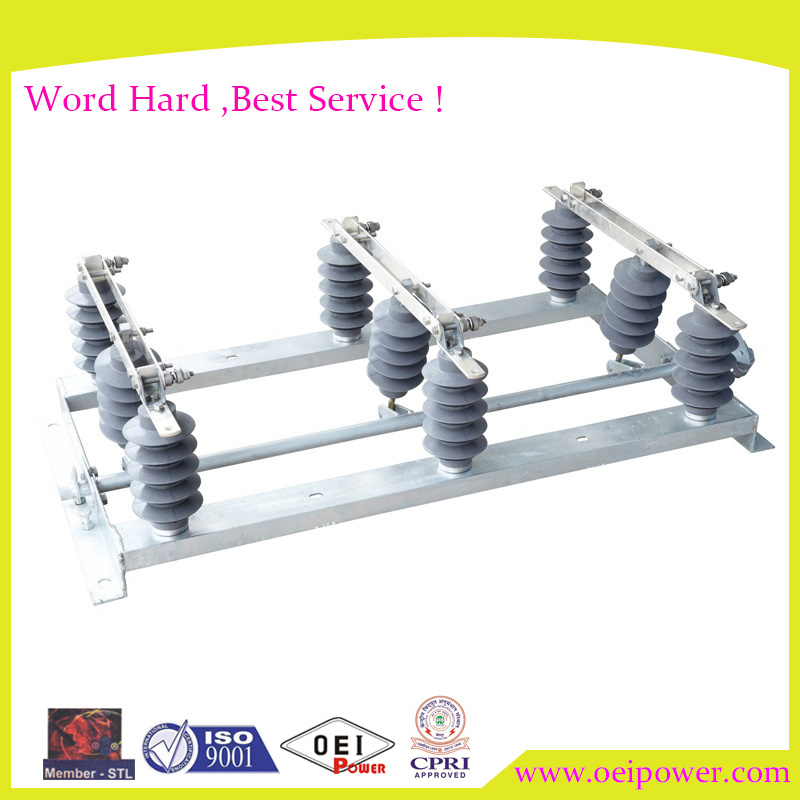
B. Insulators
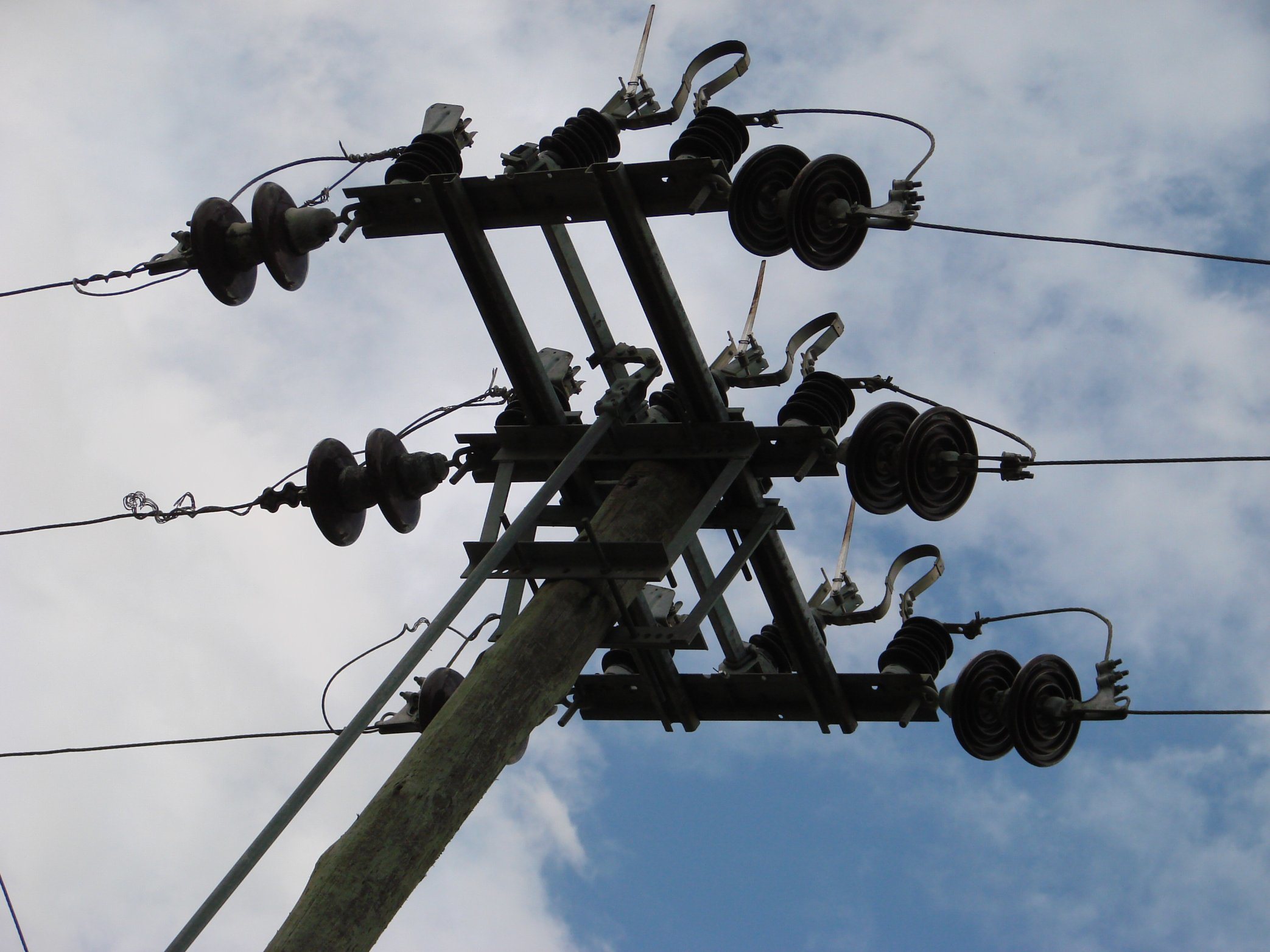
The insulators shall be of solid glazed porcelain type and be birdproof. They shall meet the electrical and mechanical characteristics indicated in IEC Standard Publication 60383. Insulators shall be based on the rated voltage of 11kV.
1. The support insulators must withstand dry and wet test voltage of 50Hz, sustained for one minute of not less than:
a. 28kV to earth and between poles and
b. 32kV across the isolating distances, re IEC 600602, Specification 3.
The Bidder shall also give the following information in the schedule.
c. The minimum dry flashover voltage value
d. The minimum wet flashover voltage value
e. The puncture voltage of insulations at 50Hz
2. Radio Interference Voltage
The maximum radio interference voltage shall be 250 microvolts measured in accordance with IEC 60437.
Minimum phase/phase and Phase/earth shall be provided by the Supplier in the Schedule.
D. Creepage Distance
Minimum leakage distance to ground shall be 300mm
E. Construction
1. Main Assembly
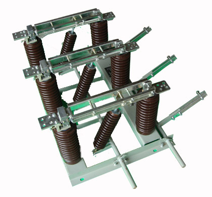
The Load Isolators shall be manually operated, mounted on a fabricated galvanized steel base and meet the following requirements.
The Load Isolator switch shall employ three-pole integer type designs and come preassembled and pre-adjusted with all three poles mounted on one-piece base with all built-in electrical clearances. It shall be suitable for outdoor use. Each pole shall be fitted with contact supporting porcelain insulators. Tripple pole rocking type isolators are not acceptable.
The interrupter chamber shall be manufactured from moulded glass-reinforced polyester and finished with a two-part urethane coating for resistance to weathering and ultraviolet radiation. The interrupter housing shall be fully gasketted to prevent entry of water. All current-carrying parts shall be manufactured from copper or copper-based materials.
The load isolator switch shall have double-member hard-drawn copper blades and silver-to-silver contacts throughout the switch. Contact construction should include a bifurcated silver-plated blade contact with stainless-steel loading spring to ensure optimum multi point contact pressure. Blade contact surfaces shall be coined for hardness, contour and low porosity.
The Load Isolators shall be designed to utilize interrupters that provide circuit interruption without external arc or flame. The interrupter contacts shall separate at high speed, be driven by a speed-multiplying straight-line linkage within the interrupter that is directly powered by blade opening or closing movement. The interrupter contacts and blade shall be synchronized to coordinate the dynamic internal dielectric strength with the interrupter external striking distance to eliminate any chance of flashover.
During switching operation, circuit interruption shall be accomplished entirely within the interrupter without external arc or flame. When the blade begins to open, the current shall be transferred to the interrupter by a shunt contact against the interrupter’s external contact before the current carrying main contacts part, followed by the arc extinction in the interrupter. During closing the sequence shall be reversed.
The disconnector switch shall be shipped in a single package ready for installation with two through-in bolt holes for mounting either single or double poles. The operating mechanism and handle shall be shipped together with the load isolator.
Arcing horns or alternative devices shall be fitted to protect contacts from erosion. (See Figure 3).
The insulators are to be rigidly connected to the base so that deflection of the insulators under short circuit conditions is kept to a minimum and there is no tendency for them to work loose from the base.
Cement used in the load isolator construction shall not cause fracture by expansion or loosening by contraction, and proper care shall be taken to locate correctly the individual parts during cementing. The cement shall not give rise to chemical reaction with metal fittings and its thickness shall be as uniform as possible.
The disconnector shall be suitable for vertical mounting on single pole.
Recommended for You
Not exactly what you want?
Post Sourcing Request
Hot Searches
Switch Box
Time Switch
Air Switch
Voltage Switch
Level Switch
We are China Lug, 2 Hole 4/0 manufacture and supplier,You can get more details with Email,you will get cheap price or factory price.
Get Latest Price Request a quote
Popular Disconnector Switch Products
High -Voltage Isolate Switch 24kv 800A
Outdoor High Voltage Disconnecting Switch/ Isolator Power
75kv Outdoor High Voltage Three Phase Isolator Disconnector Switch
Popular jgtrade1 Products
Yh10W-36, Sharp Head 36kv 10ka Surge Arrester
Polymer Composite 9kv-24kv Surge Arrester Lightning
Hy5ws-12.7/50 Zinc-Oxide Arrester
Polymer Fuse Cutout, Drop out Fuses 33kv 200A
Popular Rotary Switch Products
33kv 12.5kn Porcelan Pin-Type Insulator
Gn19 12V 3 Phase Electrical Load Break Indoor High-Voltage Isolation Switch
Seccionador Tripolar, Break Isolator, Substation
ISO Product 25 Kv Disconnect Custom Fitted Disconnector Switch
Factory Price High Voltage AC 12kv Outdoor Disconnect Switch
Popular Switch Disconnector Products
Disconnecor 24kv Disconnector Switch
High -Voltage Isolate Switch 15kv 200A
33kv Porcelan Pin-Type Insulator
High-Voltage Disconnector Switch 38kv
120kv Outdoor Disconnect Switch Three Phases 100ka
Tags: Disconnector Switch, jgtrade1, Rotary Switch, Switch DisconnectorSimilar Or Related
If you have any questions or would like to book a session please contact us.