Sleeve Insulink Ysu 2r 2W

Sleeve Insulink Ysu 2r 2W image
Get Latest Price Request a quote
Quick Details
Product Details
| Item # | Side A | Side B | Die Inde x |
Tools, Die Set Catalog Number, & (Crimps per End) | ||||
| ACS R |
Aluminum & Copper | Color Code |
ACSR | Aluminum & Copper | Color Code |
|||
| 10 | 4 | 3, 4 Str. 2 Sol. |
Orang e | 6 | 5, 6 Str. 4 Sol. #4 Al Compt |
Blue |
BG |
|
| 11 | 4 | 3, 4 Str. 2 Sol. |
Orang e | 4 | 3, 4 Str. 2 Sol. |
Orange | ||
| 12 | 4 | 3, 4 Str. 2 Sol. |
Orang e | – | 6 Sol. 8 Str. #8 Compt. |
Green | ||
| 30 | 2 | 2 Str. 1 Str. #1 Al Compt #2 Al Compt | Red | 4 | 3, 4 Str. 2 Sol. |
Orange | ||
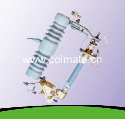
Gama 20 kV a 36 kV
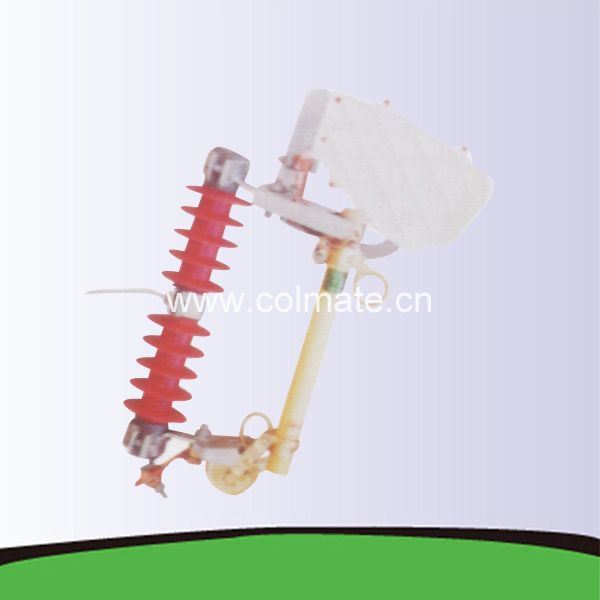
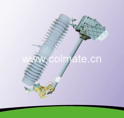
TYPE "OEI" "PRW" STANDARD CUTOUT DISTRIBUTION TECHNICAL SPECIFICATION
The Fuse Cutout type DHE was developed to operate in overhead distribution systems rated at 12-15 kV and 15-27,kV or 27-38 kV grounded systems with 100 or 200 A nominal currents.
Especially designed to protect transformers, capacitors, cables or lines.
It is robust construction, made of rigorously tested material, will interrupt all faults under the
most severe conditions, maintaining mechanical and electric characteristics.
The inserts, hardware and structural bolts and nuts are made from heavy galvanized steel.
The Fuse Cutout type OEI PRW can be applied on all three-phase system rated at or below the maximum operational rating of the cutout. In highly polluted environments or environments with high levels of salinity, a cutout may be used with a higher nominal rating than
that of the system where it is being installed, where the insulator will have a greater leakage distance to ground, allowing for
increased safety against discharge. For an even better protection against abrasions, the hardware may be supplied in stainless
steel. The fuse cutout type OEI PRW has attachment hooks in aluminum.
The Fuseholder has a stainless steel flipper, which associated with a spring doesn’t allow the fuse link to be subject to traction
forces of over 3 Kgf, especially during closing. This me chanism also allows for high speed fuse link separation. The fuse cutout
type OEI PRW allows for the insertion of the fuse tube in a precise man ner and always in perfect alignment, due to the large distance
between the grunion pocket. Lower contact, silver-to-silver, provide du el current path, independent of hinge pivot. Stainless-steel
back-up springs prevent arcing when tube rises in hinge during recoil. The fuse cutout type OEI PRW may be transformed into a DICONNECT up to 300 A, by simply changing the fuse tube for an electrolytic copper blade.
The DHE Fuse Cutouts conform to ANSI and IEC standards, with independent tests performed At:
CPRI Always use quality fuse links. Only they can assure excellent performance.
DROP OUT FUSES
| N/O | DETAIL | DATA | ||
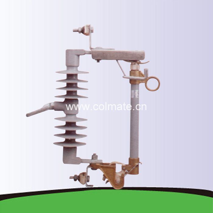
| 1 | Description | 11kV Fuse link assembly complete with fuse carrier rated at 100A and mounting bracket to PIESA 002. (See Figure 1 to Figure 12 below) |
||
| 2 | System conditions of service a) nominal Voltage (Un) r.m.s |
kV |
11 |
|
| b) maximum system voltage (Um) r.m.s | KV | 12 | ||
| c) earthing | Effective & non effective | |||
| d) Frequency | Hz | 50 | ||
| 3 | Site conditions of service a) altitude |
m |
1400 |
|
| b) Operating Ambient temperature | °C | –1 to 40 | ||
| c) Humidity | % | 85 | ||
| 4 | Rating | |||
| a) Nominal voltage | kV | 11 | ||
| b) Rated current | Fuse carrier | A |
100 |
|
| Cut out base |
A |
200 |
||
| 5 | Electrical components | |||
| a) Insulator material specification | Porcelain | |||
| Dielectric strength | ||||
| Lightning impulse withstand (1.2/50) | kV | 95 | ||
| Power frequency wet withstand voltage r.m.s |
kV | 28 | ||
| 6 | Specific creepage distance | mm/kV | 25 | |
| 7 | General information to be provided with bid: |
|||
| Drawings and brochures showing outline and general arrangement |
Yes/No |
Yes |
|
| b) Detailed drawings of all items showing critical tolerances to be provided with bid |
Yes/No | Yes | |
| 8 | Previous Type test report/certificate on complete fuse link assembly to be provided with bid |
Yes/No |
Yes |
| 10 | Routine tests (acceptance tests on sample Product) to be provided on delivery |
Yes/No | Yes |
| 11 | Applicable standard | PIESA 002 | |
| 12 | Other applicable standards | NRS 035 SABS IEC 60282–2 SABS IEC 60186 BS 137 part 2 |
3. FURTHER REQUIREMENTS:
3.1 There shall be no rivets in the parts that form the current path
3.2 Water shall not be able to accumulate on any part of the equipment nor shall any feature introduce moisture into any component.
3.3 The design shall incorporate all reasonable precautions and provisions for the safety of personnel concerned with the operation and maintenance of the same.
3.4 The current path shall be such that load current shall only flow through high conductive materials such as copper and its alloys. Load current shall not be permitted to flow through ferrous components, springs, or spring–loaded mechanisms.
3.5 All load current paths shall be so designed that the relevant parts of the solid link assembly are capable of carrying the specified rated current without exceeding the permitted temperature rise in SABS IEC 60282–2
3.6 Contacts shall be based on the line contact principle and there shall be no welds on the contact parts. The construction of the Drop out fuse base and the solid link shall ensure their mutual alignment during closure.
3.7 The solid link should have an eye and an operating tongue.
4. MARKING AND IDENTIFICATION
4.1 Markings to conform to SABS IEC 60282–2
4.2 In addition , the following markings must be included : ZESCO Indent No.
3.0 SUPPLIMENTARY NOTES
3.3 Suppliers should give sufficient information including drawings (which must be brief, clear and to the point) on how their drop out fuse designs addresses these requirements. Further, Suppliers may offer better alternatives that are of cost benefits to. It is therefore imperative that schedule "B" is completed by the tenderer. Any deviations/modifications/alternatives specification must be listed in schedule "C." No deviations/modifications/alternatives will be recognised unless they are listed in schedule "C"
3.4 The drawings to be submitted by the tenderer must include the following:
3.4.1 Critical tolerances
3.4.2 Show details of the insulator, the fuse carrier, the solid–link, the upper contact, the lower contact, the cutout base and the bracket for fixing to either wooden or steel cross arm.
3.5 The type tests to be submitted must be those issued by internationally recognised testing authority.
3.6 All salient design details of each item required shall be supplied with the tender.
33kV
| N/ O | DETAIL | DATA | ||
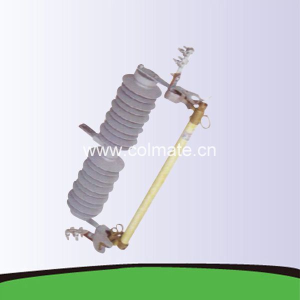
| 1 | Description | 33 kV Fuse link assembly complete with fuse carrier rated at 100A and mounting bracket to PIESA 002. (See Figure 1 to Figure 12 below) |
||
| 2 | System conditions of service a) nominal Voltage (Un) r.m.s |
kV |
33 |
|
| b) maximum system voltage (Um) r.m.s |
KV | 36 | ||
| c) earthing | Effective & non effective | |||
| d) Frequency | Hz | 50 | ||
| 3 | Site conditions of service a) altitude | m |
1400 |
|
| b) Operating Ambient temperature | °C | –1 to 40 | ||
| c) Humidity | % | 85 | ||
| 4 | Rating | |||
| a) Nominal voltage | kV | 33 | ||
| b) Rated current | Fuse carrier | A |
100 |
|
| Cut out base |
A |
200 |
||
| 5 | Electrical components | |||
| a) Insulator material specification | Porcelain | |||
| Dielectric strength | ||||
| Lightning impulse withstand (1.2/50) |
kV | 170 | ||
| Power frequency wet withstand voltage r.m.s | kV | 70 | ||
| 6 | Specific creepage distance | mm/kV | 25 | |
| 7 | General information to be provided with bid: Drawings and brochures showing outline and general arrangement |
Yes/No |
Yes |
| b) Detailed drawings of all items showing critical tolerances to be provided with bid |
Yes/No | Yes | |
| 8 | Previous Type test report/certificate on complete fuse link assembly to be provided with bid |
Yes/No |
Yes |
| 10 | Routine tests (acceptance tests on sample Product) to be provided on delivery |
Yes/No | Yes |
| 11 | Applicable standard | PIESA 002 | |
| 12 | Other applicable standards | NRS 035 SABS IEC 60282–2 SABS IEC 60186 BS 137 part 2 |
5. FURTHER REQUIREMENTS:
5.1 There shall be no rivets in the parts that form the current path
5.2 Water shall not be able to accumulate on any part of the equipment nor shall any feature introduce moisture into any component.
5.3 The design shall incorporate all reasonable precautions and provisions for the safety of personnel concerned with the operation and maintenance of the
same.
5.4 The current path shall be such that load current shall only flow through high conductive materials such as copper and its alloys. Load current shall not be permitted to flow through ferrous components, springs, or spring–loaded mechanisms.
5.5 All load current paths shall be so designed that the relevant parts of the solid link assembly are capable of carrying the specified rated current without exceeding the permitted temperature rise in SABS IEC 60282–2
5.6 Contacts shall be based on the line contact principle and there shall be no welds on the contact parts. The construction of the Drop out fuse base and the solid link shall ensure their mutual alignment during closure.
5.7 The solid link should have an eye and an operating tongue.
6. MARKING AND IDENTIFICATION
6.1 Markings to conform to SABS IEC 60282–2
3.0 SUPPLIMENTARY NOTES
3.5 Suppliers should give sufficient information including drawings (which must
be brief, clear and to the point) on how their drop out fuse designs addresses these requirements. Further, Suppliers may offer better alternatives that are of cost benefits
3.6 The drawings to be submitted by the tenderer must include the following:
3.6.1 Critical tolerances
3.6.2 Show details of the insulator, the fuse carrier, the solid–link, the
upper contact, the lower contact, the cutout base and the bracket for fixing to either wooden or steel cross arm.
3.7 The type tests to be submitted must be those issued by internationally recognised testing authority.
Recommended for You
Not exactly what you want?
Post Sourcing Request
Hot Searches
Electric Fuse
Voltage Fuse
Protection Fuse
Fuse Box
Fast Fuse
We are China Sleeve Insulink Ysu 2r 2W manufacture and supplier,You can get more details with Email,you will get cheap price or factory price.
Get Latest Price Request a quote
Popular Cut out Fuse Products
12-72.5kv Anti-Pollution Solid-Coke Post Porcelain Insulator
Grip, Preformed, 394.5mcm, Preformed
Fuse Cutout, Drop out Fuses 15kv 300A
Current-Limiting Fuse for Protection of Transformer
Self-Tightening Clamps for ACSR Conductor ‘ Sock’ Type
Popular Dropout Fuse Products
Polymer Fuse Cutout, Drop out Fuses 15 Kv 100A
Hot Selling Factory 12kv 100A Dropout Porcelain Fuse Cutout
30kv Porcelain Housed Cutout Fuse Cfi27kv-33kv
Fuse Cutout, Drop out Fuses 36kv 300A
24kv Composite Cutout Fuse Polymer Dropout Fuse Silicon Fuse Cutout Gang Insulator
Popular Fuse Cutout Products
Polymer Fuse Cutout, Drop out Fuses 21 Kv 100A
12kv Outdoor Expulsion Drop-out Type Distribution Fuse Cutout
Outdoor Expulsion Drop out Type Distribution Fuse Cutout
Fuse Cutout, Drop out Fuses 33kv 900A
15kv 100A/200A Polymer Expulsion Fuse Cutout
High-Voltage Polymer Drop-out Fuse Cutout
Popular jgtrade1 Products
High Temperature-Resistant Gloves (aluminium foil)
Fuse Cutout, Drop out Fuses 24kv 100A 20ka
Price Overhead Power Line 11kv Dropout Fuse Cutout
Parallel Groove Copper Aluminum Clamps
Box Type Fixed Totally Enclosed Switchgear
Tags: Cut out Fuse, Dropout Fuse, Fuse Cutout, jgtrade1Similar Or Related
-

11kv Composite Cutout Fuse Polymer Dropout Fuse Silicon Fuse Cutout
-
15kv Composite Cutout Fuse Polymer Dropout Fuse Silicon Fuse Cutout
-
33kv Composite Cutout Fuse Polymer Dropout Fuse Silicon Fuse Cutout
-
24 Kv Porcelain Cutout Fuse Ceramic Dropout Fuse Fuse Cutout Gang Insulator
-
33 Kv Porcelain Cutout Fuse Ceramic Dropout Fuse Fuse Cutout Gang Insulator
If you have any questions or would like to book a session please contact us.