Design Expulsion Fuse (PRW-15)

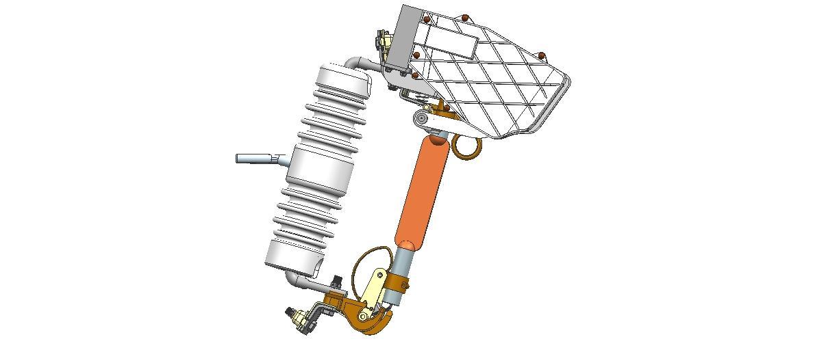
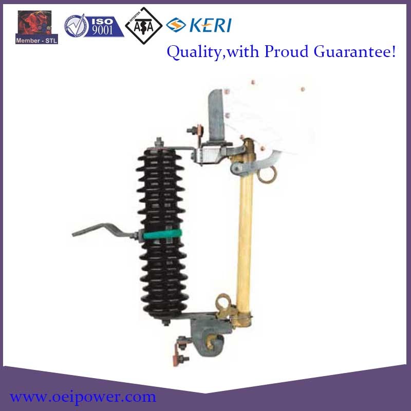
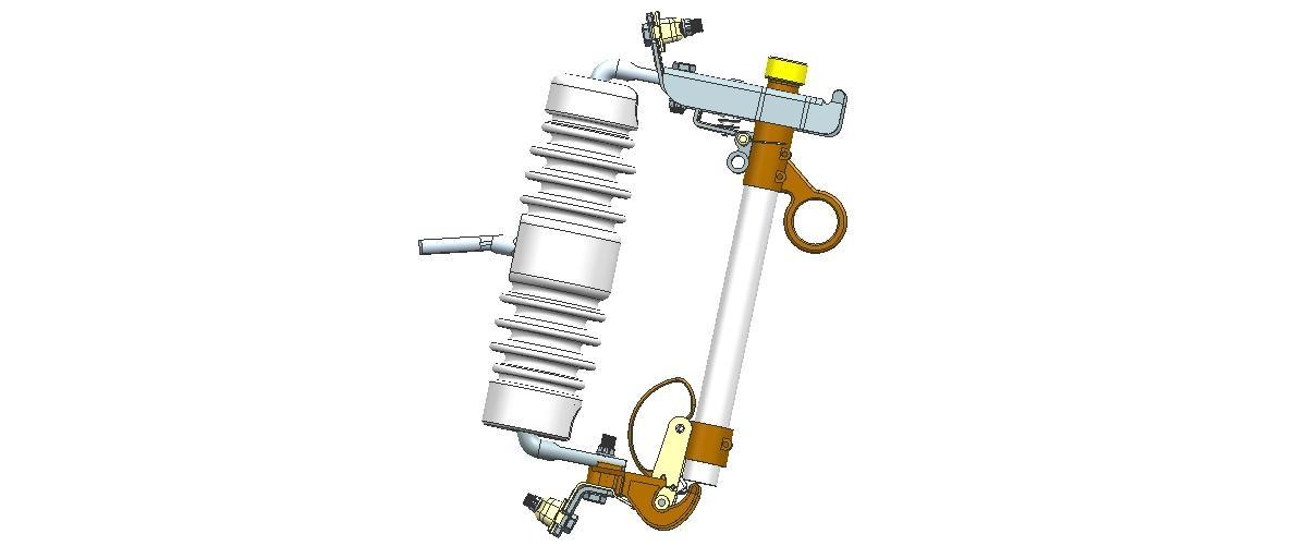
Design Expulsion Fuse (PRW-15) image
Get Latest Price Request a quote
Quick Details
Product Details
DESIGN EXPULSION FUSEGEAR
The complete assemblies shall be rated 105°C for normal circuit conditions. Further they shall meet the following electrical test requirements.
1. Voltage
a. BIL: 170kV, 1.2 x 50 microsecond wave.
b. AC Withstand: 70kV, 50Hz, 1 minute; dry and wet.
2. Current
a. Continuous Operation: 100A minimum
b. Rated interrupting current of Expulsion fusegear:
Prospective RMS symmetrical amperes: 4000A, i.e. 6 tests of test Series No. 1 from total series of 16 tests per Table IVA IEC 602822 at 4,000 amperes RMS symmetrical.
3. Low Current Interruption
The Expulsion fusegear shall meet the requirements of IEC 602822 Clause 13, and shall be tested to interrupt down to 15 amperes applied to a 6K fuse link.
4. Fuse Link Range and Class
The Expulsion fusegear shall be suitable in all respects for fuse links within the range 1 to 100 amps per IEC and NEMA standards.
B. Interchangeability
The fuse holder (tube) of a fuse isolator shall be dimensionally compatible with a universal fuse link of corresponding rating and with a universal fuse tube.(e.g. fuse links manufactured by Hubbell Power Systems and S&C Electric Company of North America)
C. Insulators
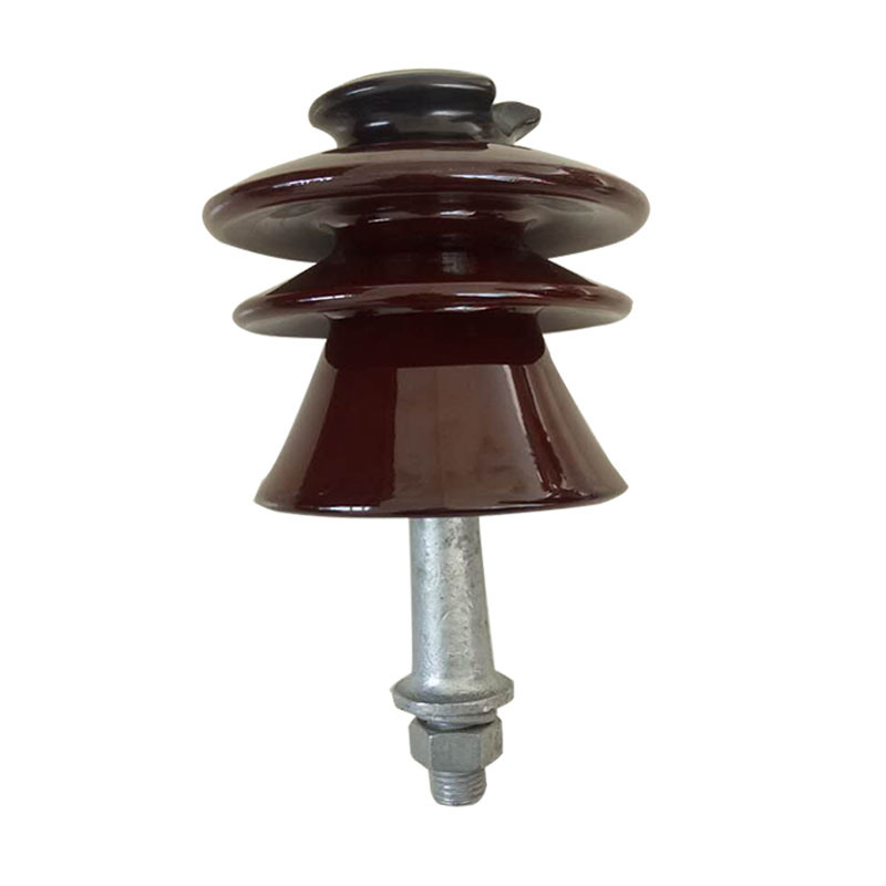
The insulators shall be of solid glazed porcelain type and be birdproof. They shall meet the electrical and mechanical characteristics as shown in IEC Standard Publication 60383. Insulators shall be based on rated voltage of 33kV.
a. 70kV to earth and between poles and
b. 80kV across the isolating distances, re IEC 600602, Section 3
The Supplier shall also give the following information in the schedule.
c. The minimum dry flashover voltage value
d. The minimum wet flashover voltage value
e. The puncture voltage at 50Hz.
2. Radio Interference Voltage
The maximum radio interference voltage shall be 250 microvolts measured in accordance with IEC 60437.
D. Clearance
The Supplier shall give the following information in the schedule:
1. Minimum phase/phase clearance
2. Minimum phase/earth clearance.
E. Creepage Distance
Minimum leakage distance to ground shall be 900mm.
F. Construction
1. Main assembly
a. The main assembly may be mounted on a 2 insulator channel base arrangement. The insulators shall be porcelain and bird proof.
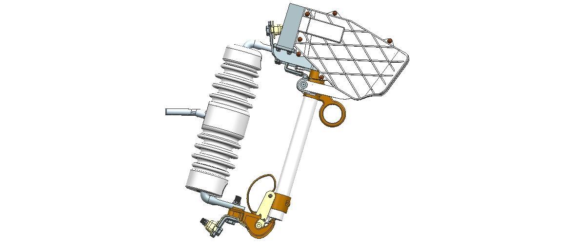
Top and bottom contact subassemblies and mounting fitting shall be potted into the porcelain insulators. The upper fixed contacts shall positively latch. (See Figures 1 and 2).
b. All contacts shall be designed to give permanent current carrying capacity at rated current after exposure to marine climate for up to 20 years. All current carrying components shall be of copper or copper alloy. Terminals shall be suitable for conductor up to 265mm2 Al/Cu.
c. Contacts shall be heavily silver clad on each side of each interface. Embossed surfaces with wiping action are preferred.
d. Ferrous components shall be stainless steel or galvanised. The Supplier shall state weight/thickness of zinc coating on the attached Schedule.
e. The Expulsion Fusegear shall be provided with a permanently fitted loadbreak device.
f. The assembly shall be designed such that the fuse tube can be closed without using undue care even when the closing force is applied from an angle.
g. The angle of fuse tube relative to the vertical shall be filled in on the attached schedule.
h. The insulator shall preferably be marked with the rated voltage and the minimum basic insulation level
IEEE/NEMA brackets shall be provided.
2. Fuse Tube Assembly
a. The fuse tube shall be capable of accepting IEC/NEMA fuse links up to a maximum continuous current rating of 100 amperes.
b. The toggle mechanism shall provide locking action to protect the fuse link from shock. A spring assisted flipper shall assist arc interruption by withdrawal of the fuse tail.
c. The fuse tube cap may be the expendable type.
d. A lifting eye shall be provided on the fuse tube and designed for use with hookstick.
e. The fuse tube shall be permanently marked with the following: Supplier/Manufacturer; model; maximum continuous current rating; rated maximum voltage phase to phase; rated symmetrical amperes interrupting per IEC requirements.
G. Operating Gear
For Single Pole Units operation will be by means of the Purchaser’s standard operating hot-stick, and loadbreak tool to ensure existing practice can continue.
We are China Design Expulsion Fuse (PRW-15) manufacture and supplier,You can get more details with Email,you will get cheap price or factory price.
Get Latest Price Request a quote
Popular Chave Fusivel Polimerica Products
Insulator 500kv 12.5kn_DSC3521--1
Popular Interrupter Products
Switch Disconnector Fuse Holder, 18 Kv - 200 AMP, Without Arc Chute
Polymer High-Voltge Expulsion Type Distribution Type Fuses
Switch Disconnector Fuse Holder, 27 Kv - 200 AMP, Without Arc Chute
Terminal Connectors Bolted Type, Type SL, Group C
Popular jgtrade1 Products
Gw4-126 Outdoor AC Disconnector Switch Manufacturer Horizontal Opening
Stepping Board (white palm rope)
OEM Accept High Voltage Outdoor Disconnect Switch Disconnector
Polyester Lined Glove Coated with PU (black)
Various Types of Transformers Beams
Popular Loadbreak Cutout Products
Surge Arresters 30kv Mounted on Crossarm
Fully Sealed and Fully Insulated Inflatable Ring Network Switchgear
Terminal Connectors Bolted Type, Type SL, Group C
Tags: Chave Fusivel Polimerica, Interrupter, jgtrade1, Loadbreak Cutout

